| - VHF SYNTOR X 9000 TOUR | |||
| - Bottom View | |||
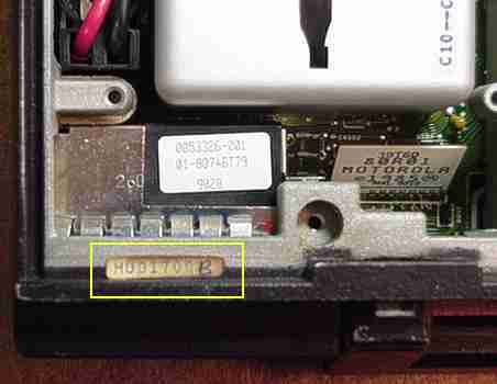
| - Unified Chassis Number | |||
| - VHF Receiver Standard Filter & Optional Preamplifiers | |||
| - VCO | |||
| All Photos by: Max KK7HI | |||
| -Syntor X 9000 Home | |||
| - HOME | |||
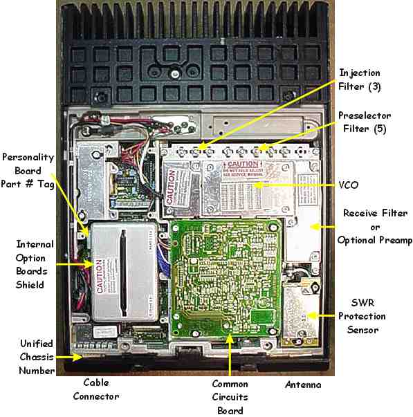
This page is a visual tour of a VHF Syntor X 9000 radio. To access this part of the radio, first the key is used to open the handle, then the mounting tray is removed (it slides off the bottom and can be stubborn), then the radio is turned over, the 4 screws are loosened and the bottom cover removed. If the mounting tray was already removed then the key is not needed. This is a bottom view of the radio. You can click on different parts of the radio photograph to get more information or a closeup photograph. If you locate the Unified Chassis Number you can use the Syntor X model page to lookup detailed information on the radio.
The 4 screws on the bottom cover may be Phillips or Torex screws. These screws have a keeper on them so they only have to be loosened until they release the bottom cover from the radio (they will remain attached to the bottom cover).
The Unified Chassis Number location, Receive Filter, optional Preamplifier, VCO, Preselector and Injection Filters are the same for the VHF Syntor X 9000. The Syntor X 9000 model page should be used to lookup Syntor X 9000 Unified Chassis Numbers.
Sorry, this page will take a while to load on slow connections.
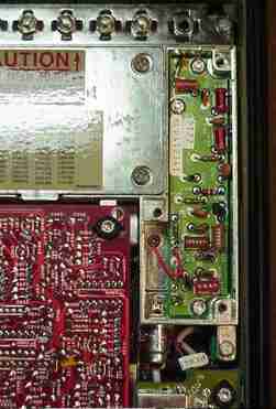
The Unified Chassis Number tag has been highlighted with a yellow border. When the radio's bottom cover is in place it partially obscures the tag. Tags are the most common means of marking the radios and sometimes they have come off or have been removed leaving the Unified Chassis Number a mystery (pictures below can be used to identify an optional preamp).
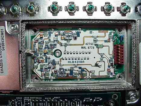
Notice the large empty area in the middle of the board where the part number tag is located. There are no transistors on this board. One of the two optional receiver preamps (below) can be substituted for this board depending on the radio range. Decoding the Unified Chassis Number or opening the compartment will tell you if the radio had an optional Rx preamplifier or not. The cover and shield were removed (3 screws) for the photo.
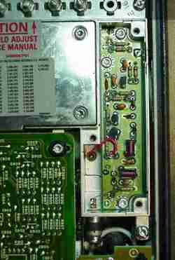
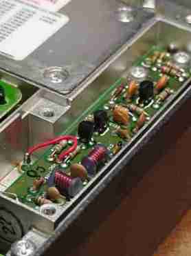
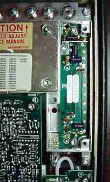
Notice the 3 transistors on this board (small black packages). The cover and shield were removed (3 screws) for the photo.
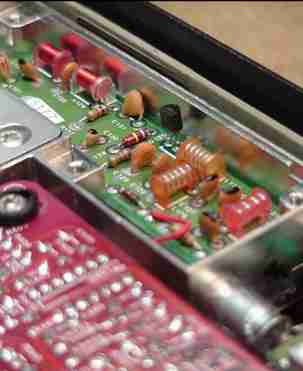
Notice the single field effect transistor on this board (small black package). The cover and shield were removed (3 screws) for the photo.
Notice the two horizontal Microstrip Tuning Pads (9 pads in each of 2 rows) in the middle of the VCO circuit board. The 9 top horizontal Microstrip Tuning Pads are for the receiver and the wire is cut between the 5th and 6th pads (counting from the left). The 9 bottom horizontal Microstrip Tuning Pads are for the transmitter and the wire is cut between the 3rd and 4th pads (counting from the left). Both of these pads are connected to the VCO circuit from the left side. So the receiver has 4 isolated pads after the cut wire and the transmitter has 6 isolated pads after the cut wire. These cuts were made by Motorola at the factory to tune the VCO frequency range. The range 1 VCO looks similar, except there are 10 receiver Microstrip Tuning Pads and 11 transmitter Microstrip Tuning Pads. The VHF VCO is the only VCO to have separate receive and transmit Microstrip Tuning Pads. The VCO cover was removed (4 screws) for the photo.
--
PL, Private Line, DPL, Digital Private Line, MPL, Talkaround, MDC-600, MDC-1200, MVS-20, Securenet, Smartnet, Privacy Plus, Trunked X2, Trunked X3, Touch Code, Quick Call II, Channel Scan, Talkback Scan, System 90, System 90*s, Systems 9000, Mitrek, Micor, Spectra, MataTrac, Syntor, Syntor X, Syntor X 9000 and Syntor X 9000E are trademarks of Motorola Inc.