Mike Blenderman, K7IC passed in 2022. This December 2021 mirror
of his onfreq.com site was extracted from the Wayback Machine.
[SYNTOR]
[SYNTOR X] [SYNTOR X 9000
and X 9000E] [TRUNKING SYNTOR
X and SYNTOR X 9000] [SPECTRA]
[INTRODUCTION]
[NEW RADIO INSPECTION] [NEW RADIO MODIFICATIONS] [FAIL AND ERROR CODE PREFIXES]
[SYSTEMS 9000] [PROGRAMMING]
[SYNTOR X 9000 CONVERSIONS] [MODELS] [MANUALS]
[CONTROL HEADS] [DEKS]
[CABLES] [BOARDS] [PARTS]
[OPTIONS and ACCESSORIES] [SYNTOR
X 9000 VISUAL TOUR]
[PL] [DPL] [PAC-PL
and PAC-RT VEHICLE REPEATERS][HHCH] [PROM
PROGRAMMERS] [POWER
WIRING]
[GLOSSARY]
[WEB LINKS] [SURPLUS
PARTS GUIDE] [ITEMS FOR SALE]
[WEB SITE REVISIONS]
Radio trouble shooting tip:
Sometimes a radio can have intermittent operation and/or generally
flakey problems that can be attributed to dirty, loose or oxidized
connections on the A or B power terminals (these are connected
to the large gauge red and black power wires). Checking and if
needed, cleaning or repairing these connections can fix lots of
different problems with these radios. Motorola started covering
the back side of these 2 connections (inside the connector housing)
with a glob of epoxy on later production cables (it also gets
on the connector body and adjacent wires). Actually the epoxy
makes repair/replacement just about impossible, but they should
not have problems very often, if ever. I would not recommend
using any epoxy on used cables because of the possibility of old
pre-existing partially oxidized connections that you would never
be able to repair again if they go bad. This tip applies to any
other accessories (i.e. Systems 9000 siren/PA, Systems 9000 vehicle
repeater, Systems 9000 External Options Housing, etc.) that use
these connectors.
Syntor X 9000 Radio Cable Pin
Out:
Below is a pin number locater for the radio cable connector.
The view is looking towards the pins that plug into the radio's
J1 connector with the cable on the left side. Motorola's contact
removal tool or a home made equivalent can be used to remove
and move the number 1 through 37 contact pins in these connectors.
To open the connector housing the neoprene gasket corners must
be pulled up to gain access to the 4 phillips head screws. Removing
these screws allows the housing on the back of the connector to
be removed. The C clip on the center screw jack must also be removed.
It is difficult, actually impossible sometimes, to peel back the
neoprene without damaging it. I have seen connectors where just
the part of the neoprene gasket over the 4 screw heads was removed.
The gasket may need to be replaced if you want to maintain the
original connector sealing.
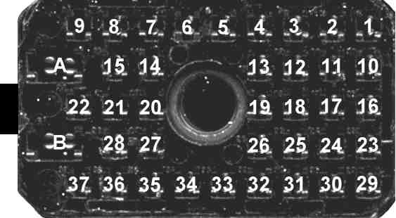
- Above is a front view of the radio cable connector.
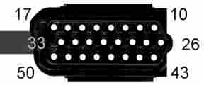
- Above is a front view of the cable's control head connector with
pin numbers. Each of the three horizontal rows of pins is numbered
sequentially from right to left. The cable is on the left side of the
connector.
| Syntor X 9000 Cable Pin Out (Negative Ground) |
Radio
J1 Pin # |
Wire
Color |
Control
Head Pin # |
Radio Pin
Description |
| A |
Red |
|
A+ |
| B |
Black |
|
A- (jumpered to pins
8 and 10) |
| 1 |
|
|
PTT (Input) |
| 2 |
BLK/BRN |
45 |
Detected Audio (Output) |
| 3 |
BLK/GRN |
46 |
Option Tx Audio (Input) |
| 4 |
BLK/ORG |
26 |
Reset (Input/Output) |
| 5 |
BLK/RED |
33 |
Busy (Input/Output) |
| 6 |
YEL |
48 |
Switched B+ (Input) |
| 7 |
|
|
Switched B+ (Output) |
| 8 |
|
|
B- (jumpered to pins
10 and B) |
| 9 |
|
|
Filtered
Audio (Output) |
| 10 |
|
|
Chassis (jumpered to
pins 8 and B) |
| 11 |
Shield |
|
Detected Audio Shield |
| 12 |
|
|
A+ (later versions only -
see below) |
| 13 |
RED |
29 |
Spare 2 |
| 14 |
Shield |
13 |
Mic. Low |
| 15 |
|
|
Filtered Audio Shield |
| 16 |
red* |
port pin 1* |
Write Enable (Input) |
| 17 |
WHT |
17 |
Bus + (RS-422
Input/Output) |
| 18 |
Shield |
|
Option Tx Audio Shield |
| 19 |
Shield |
|
Bus - Shield |
| 20 |
|
|
B- |
| 21 |
|
|
Channel Activity (Output) |
| 22 |
GRN |
11 |
Speaker Audio Low (Output) |
| 23 |
yel* |
port pin 2* |
KEY (Input) |
| 24 |
BRN |
28 |
Spare 1 |
| 25 |
BLK |
50 |
Bus - (RS-422
Input/Output) |
| 26 |
VIO |
16 |
Analog Ground |
| 27 |
BLK/YEL |
12 |
Mic. Hi (Input) |
| 28 |
|
|
|
| 29 |
wht* |
port pin 5* |
KID |
| 30 |
|
|
|
| 31 |
blk* |
port pin 4* |
B- |
| 32 |
BLU |
49 |
B- |
| 33 |
|
|
Option Rx Audio (Input) |
| 34 |
blk* |
port gnd.* |
Option Rx Shield |
| 35 |
|
|
|
| 36 |
|
|
|
| 37 |
ORG |
44 |
Speaker Audio Hi (Output) |
- This cable goes from the Syntor X 9000 radio and connects to the
Systems 9000 Control Head. This includes HKN4240A, HKN4241A, HKN4242A and HKN4256A
cables.
- The grayed out pins are not used on these radio cables. The
keyloader port pins are highlighted in green and are are only included
on the HKN4256A cable.
- Pin 12 Note: Connector J1 Pin 12 was not connected in
early versions of the Personality Board. The HKN4295A
and HKN4304A cables require this connection to
operate (i.e. it must be jumpered on early versions of the Personality
Board). This problem can affect the SirenPA, External Options Housing
and Vehicle Repeater System (VRS).
- * - HKN4256A Securenet cable with keyloader port. The keyloader
port is located on a special J1
connector front housing. The keyloader port pins are highlighted in
green.
Systems 9000 Control Head to
Radio Pin Out:
- Above is a front view of the cable's control head connector with
pin numbers. Each of the three horizontal rows of pins is numbered
sequentially from right to left. The cable is on the left side of the
connector.
- Above is a front view of the cable's radio connector with pin
numbers. The cable is on the left side of the connector.
| Systems 9000 Control Head to Radio Pin Out |
| Control
Head Pin # |
Radio
J1 Pin # |
Description |
| 10 |
|
Speaker Audio Low (Output) (BLK/GRN Wire) |
| 11 |
22 |
Speaker Audio Low (Input) |
| 12 |
27 |
Mic. Hi (Output) |
| 13 |
14 |
Mic. Low (Output) |
| 14 |
|
BATT- (shorted to Pin 31) |
| 15 |
|
Ignition + (Input) (Orange wire) |
| 16 |
26 |
ANALOG GROUND |
| 17 |
17 |
Bus + (RS-422
Input/Output) |
|
| 26 |
4 |
Reset (Input/Output) |
| 27 |
|
(N.C.) |
| 28 |
24 |
Spare 1 |
| 29 |
13 |
Spare 2 |
| 30 |
|
BATT+ (shorted to Pin 47) |
| 31 |
|
BATT- (shorted to Pin 14) |
| 32 |
|
Ignition - |
| 33 |
5 |
Busy (Input/Output) |
|
| 43 |
|
Speaker Audio Hi (Output)
(BLK/ORG Wire) |
| 44 |
37 |
Speaker Audio Hi (Input) |
| 45 |
2 |
Detected Audio
(Input) (N.C.) |
| 46 |
3 |
Option Tx Audio
(Output) (N.C.) |
| 47 |
|
BATT+ (Input) (Green Wire) (shorted to Pin 30) |
| 48 |
6 |
Switched B+ (Output) |
| 49 |
32 |
DIGITAL GROUND |
| 50 |
25 |
Bus - (RS-422
Input/Output) |
- These are the same cables as above, it
is just being shown from the control head side of the cable.
- N.C. means there is No Connection inside the control head.
- The grayed out Control Head Pin #s are not used on the
negative ground cable. Some Radio J1 pin #s are grayed out
because the control head pins are connected to external wires that do
not go back to the radio.
- The yellow highlighted pins with a wire
indicated in the description do not go to the radio. These wires
are only attached to the control head connector.
- The input and output notes in parenthesis are with respect to the
control head.
- For negative ground cables, the green wire (BATT+) and orange
wire (IGN+) that are attached to the control head side of the radio
cable need to be fused and attached to the battery + voltage. The green
wire provides power to the control head. The orange wire is used in
conjunction with the RSS programming. If the orange wire is attached to
an automotive circuit that is only on when the ignition key is on, the
radio can be programmed to only allow transmitting when the ignition
key is on.
- Some radios and control heads are modified so the control head
draws power from the radio instead of the green control head connector
wire. Usually a Spare line is used to carry power to the radio. The
modification to the control head can be as subtle as a solder blob
between pins 29 (Spare 2) and 30 (BATT+). Personally, I would not do
this modification unless I could figure out how to fuse the Spare line
inside the radio. However, you may encounter this modification in used
radios and control heads.
- The HCN1063 and HCN1073 control heads have internal jumpers that
can reconfigure some of the control head pins such that the
descriptions above would no longer be correct for those control head
pins. Other models of control heads should be checked for physical
modifications (i.e. cut PC traces, wire jumpers and extra components
soldered point to point on the PC board) that can have the same effect
on the description. Expect to find modifications on control heads with
a kit number below the model number.
- Check out the parts page for
the conector and pins that mate with the cable's speaker connector.
- If the retainer clips are broken off of the control head
connector, use REX-1070B as a
replacement.
Systems 9000 Control Head to
Microphone Pin Out:
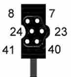
- Above is a front view of the microphone control head connector
with pin numbers. The microphone cord is hanging down below the
connector.
| Systems 9000 Control Head Microphone Pin Out |
| Control
Head Pin # |
Description |
| 7 |
Mic. Low (Input)
- Black |
| 8 |
Mic. Hi (Input)
- Red |
|
| 23 |
PTT/HUB Reference (Input)
- White |
| 24 |
PTT (Input) -
Green |
|
| 40 |
Hang Up Box (HUB) (Input)
- Blue |
| 41 |
Switched B+ (Output)
- Yellow |
- The input and output notes in parenthesis are with respect to the
control head.
- The colors shown are for the cable wires inside the microphone
housing. Most microphone cables do not have the yellow Switched B+
wire.
- The HCN1063 and HCN1073 control heads have internal jumpers that
can reconfigure some of the control head pins such that the
descriptions above would no longer be correct for those control head
pins. Other models of control heads should be checked for physical
modifications (i.e. cut PC traces, wire jumpers and extra components
soldered point to point on the PC board) that can have the same effect
on the description. Expect to find modifications on control heads with
a kit number below the model number.
- One reconfiguration example is the control head pin 41 can be
changed from Switched B+ to Speaker Audio Hi. This
could be done for a telephone style handset.
Systems 9000 Control Head to
VIP Pin Out:
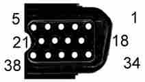
- Above is a front view of the Vehicle Interface Port (VIP) control
head connector with pin numbers. Each of the three horizontal rows of
pins is numbered sequentially from right to left.
| Systems 9000 Control Head to Vehicle Interface Port Pin Out |
| Control
Head Pin # |
Description |
| 1 |
VIP Out 2 (Output) |
| 2 |
VIP Out 1 (Output) |
| 3 |
VIP In 2 (Input) |
| 4 |
VIP In 1 (Input) |
| 5 |
DEK Data Out (Output) |
|
| 18 |
Switched B+ (Output) |
| 19 |
Switched B+ (Output) |
| 20 |
DIGITAL GROUND |
| 21 |
DIGITAL GROUND |
|
| 34 |
VIP Out 3 (Output)
/ DEK Strobe (Output) |
| 35 |
Switched B+ (Output) |
| 36 |
DIGITAL GROUND |
| 37 |
VIP In 3 (Input)
/ DEK Data In (Input) |
| 38 |
DEK Clock (Output) |
- The input and output notes in parenthesis are with respect to the
control head.
- The HCN1063 and HCN1073 control heads have internal jumpers that
can reconfigure some of the control head pins such that the
descriptions above would no longer be correct for those control head
pins. Other models of control heads should be checked for physical
modifications (i.e. cut PC traces, wire jumpers and extra components
soldered point to point on the PC board) that can have the same effect
on the description. Expect to find modifications on control heads with
a kit number below the model number.
Sytems 9000 Direct Entry Keyboard
(DEK) Cable Pin Out:
- Above is a front view of the Vehicle Interface Port (VIP) control
head connector with pin numbers. Each of the three horizontal rows of
pins is numbered sequentially from right to left. The cable is not
shown as it comes straight out of the back of the connector.
- Above is a front view of the DEK connector with pin numbers. The
cable is hanging down below the connector.
| Systems 9000 DEK Cable Pin Out |
Control
Head VIP
/ DEK J1
Pin # |
DEK J1
Pin # |
DEK
Description - VIP Description |
| 1 |
|
N.C. |
| 2 |
|
N.C. |
| 3 |
|
N.C. |
| 4 |
|
N.C. |
| 5 |
40 |
DEK Data Out (5 Output, 40 Input) |
|
| 18 |
|
N.C. |
| 19 |
|
N.C. |
| 20 |
|
N.C. |
| 21 |
|
N.C. |
|
| 34 |
24 |
DEK Strobe (34 Output, 24 Input) VIP
Out 3 |
| 35 |
41 |
Switched B+ (Input) |
| 36 |
7 |
Ground |
| 37 |
8 |
DEK Data In (37 Input, 8 Output) VIP
In 3 |
| 38 |
23 |
DEK Clock (38
Output, 23 Input) |
- The input and output notes in parenthesis are with respect to a
DEK.
- The large connector on the back of the DEK looks like a Systems
9000 control head connector. In reality, the DEK connector pins that
would appear to be Systems 9000 microphone pins are in fact the DEK
interface pins, the pins that would appear to be Systems 9000 VIP pins
are in fact connections for another DEK (i.e. the DEK expansion port)
and the pins that would appear to be Systems 9000 Control Head
Connection pins are in fact VIP II pins (see below).
- When a DEK is connected to a control head, the DEK cable (larger
cable connector) is connected to the control head VIP port (pins listed
above) and to the DEK connector (smaller cable connector) where it
looks like a microphone should go (pins listed above).
- When a DEK is connected to another DEK, the DEK cable (larger
cable connector) is connected to the DEK expansion port (pins listed
above) and to the second DEK connector (smaller cable connector) where
it looks like a microphone should go (pins listed above).
- From the table above, it would appear the DEK uses VIP 3 input
and output. This is not really the case and the VIP 3 input and output
pins are moved to the VIP II pins (see below) on the first DEK.
Systems 9000 Direct Entry Keyboard
(DEK) VIP II Pin Out:
- Above is a front view of the DEK Vehicle Interface Port (VIP) II
control head connector with pin numbers. Each of the three horizontal
rows of pins is numbered sequentially from right to left. Ignore the
cable shown in this picture, this connector (15-80212L01) does not have
a molded in cable.
| DEK Vehicle Interface Port II Pin Out |
| DEK
VIP II Pin # |
Description |
| 10 |
Ground |
| 11 |
Ground |
| 12 |
Ground |
| 13 |
N.C. |
| 14 |
N.C. |
| 15 |
VIP In 1 (Input) |
| 16 |
VIP In 2 (Input) |
| 17 |
VIP In 3 (Input) |
|
| 26 |
N.C. |
| 27 |
N.C. |
| 28 |
N.C. |
| 29 |
N.C. |
| 30 |
N.C. |
| 31 |
N.C. |
| 32 |
N.C. |
| 33 |
N.C. |
|
| 43 |
VIP Out 1 (Output) |
| 44 |
VIP Out 2 (Output) |
| 45 |
VIP Out 3 (Output) |
| 46 |
N.C. |
| 47 |
N.C. |
| 48 |
Switched B+ (Output) |
| 49 |
Switched B+ (Output) |
| 50 |
Switched B+ (Output) |
- The input and output notes in parenthesis are with respect to the
DEK.
- The grayed out pins are not used.
- Because the DEK uses the control head VIP connector pins, the VIP
connection is automatically moved to the DEK (when you change the
control head RSS number of DEKs setting to be higher than zero), on the
side of the DEK connector that looks like it would normally
have been used for a Systems 9000 Control Head to Radio connection.
This relocated VIP connector was renamed the VIP II connection.
- The first DEK replaces the VIP connections (on its VIP II
connector) that used to come from the Systems 9000 control head. A
second DEK adds another complete set of VIP pins on its VIP II
connector. The control head RSS is used to program these pins.
- The VIP II connector housing
could be used for a "roll your own" radio cable connector and plugged
into a Systems 9000 control head instead of a DEK.
- If you add two DEK's to a control head, each DEK has its own VIP
II connector, giving you a total of 6 VIP input pins and 6 VIP output
pins. The functions for all these pins are programmed by the control
head RSS.
Syntor X 9000 Radio Securenet Physical
Security Housing Cable Pin Out:
- Above is a front view of the cable's radio connector with pin
numbers. The cable is on the left side of the connector.
Syntor X 9000 Radio Physical Security Housing Cable
Pin Out (Negative Ground) |
Radio
J1 Pin # |
Wire
Color |
Security
Housing
Pin # |
Radio Pin
Description |
| A |
Red |
|
A+ |
| B |
Black |
|
A- (jumpered
to pins 8 and 10) |
| 1 |
|
|
PTT (Input) |
| 2 |
BLK/BLU |
18 |
Detected Audio (Output) |
| 3 |
BLK/GRN |
19 |
Option Tx Audio (Input) |
| 4 |
VIO |
5 |
Reset (Input/Output) |
| 5 |
BLK/RED |
21 |
Busy (Input/Output) |
| 6 |
YEL |
6 |
Switched B+ (Input) |
| 7 |
|
|
Switched B+ |
| 8 |
|
|
B- (jumpered
to pins 10 and B) |
| 9 |
|
|
Filtered
Audio (Output) |
| 10 |
|
|
Chassis (jumpered
to pins 8 and B) |
| 11 |
Shield |
17 |
Detected Audio Shield |
| 12 |
|
|
A+ (later
versions only) |
| 13 |
RED |
15 |
Spare 2 |
| 14 |
Shield |
10 |
Mic. Low |
| 15 |
|
|
Filtered
Audio Shield |
| 16 |
|
|
Write Enable
(Input) |
| 17 |
WHT |
7 |
Bus + (RS-422 Input/Output) |
| 18 |
Shield |
20 |
Option Tx Audio Shield |
| 19 |
Shield |
9 |
Bus - Shield |
| 20 |
|
|
B- |
| 21 |
|
|
Channel
Activity |
| 22 |
ORG |
12 |
Speaker Audio Low (Output) |
| 23 |
|
|
KEY (Input) |
| 24 |
WHT/RED |
14 |
Spare 1 |
| 25 |
BLK |
8 |
Bus - (RS-422 Input/Output) |
| 26 |
VIO |
16 |
Analog Ground |
| 27 |
BLK/YEL |
4 |
Mic. Hi (Input) |
| 28 |
|
|
|
| 29 |
|
|
KID |
| 30 |
|
|
|
| 31 |
|
|
B- |
| 32 |
BLU |
24 |
B- |
| 33 |
BLK/BRN |
3 |
Option Rx Audio |
| 34 |
Shield |
11 |
Option Rx Shield |
| 35 |
|
|
|
| 36 |
|
|
|
| 37 |
GRN |
13 |
Speaker Audio Hi (Output) |
- This cable goes from the Syntor X 9000 radio and connects to the
24 pin Securenet Physical Security Housing connector. This includes HKN4289A and HKN4293A cables.
- The grayed out pins are not used.
Systems 9000 Control Head Securenet
Physical Security Housing Cable Pin Outs:
| 1 |
2 |
3 |
4 |
5 |
6 |
7 |
8 |
9 |
10 |
11 |
12 |
13 |
14 |
15 |
16 |
17 |
18 |
19 |
20 |
21 |
22 |
23 |
24 |
- Above is a front view of the cable's J2 / J5 Physical Security
Housing connector pin numbers.
- Above is a front view of the cable's control head connector with
pin numbers. Each of the three horizontal rows of pins is numbered
sequentially from right to left. The cable is on the left side of the
connector.
HKN4290A
/ HKN4292A Physical Security Housing to Control Head
Systems 9000 Cable Pin Out (Negative Ground) |
Housing
J2 / J5
Pin # |
Wire
Color |
Control Head
Pin # |
Pin Description |
| 1 |
|
|
A+ (Input) |
| 2 |
BLK/YEL |
12 |
Mic. Hi In (Input) |
| 3 |
|
|
Option Rx Audio (Input) |
| 4 |
|
|
Mic. Hi Out (Output) |
| 5 |
BLK/ORG |
26 |
Reset (Input/Output) |
| 6 |
YEL |
48 |
Switched B+ (Input) |
| 7 |
WHI |
17 |
Bus + (RS-422 Input/Output) |
| 8 |
BLK |
50 |
Bus - (RS-422 Input/Output) |
| 9 |
Shield |
9 |
Bus Shield |
| 10 |
Shield |
13 |
Mic. Low |
| 11 |
|
|
Option Rx Audio Shield |
| 12 |
GRN |
11 |
Speaker Audio Low (Output) |
| 13 |
ORG |
44 |
Speaker Audio Hi (Output) |
| 14 |
BRN |
28 |
External Key Reset / CH Spare 1 |
| 15 |
RED |
29 |
S.NET LED / CH
Spare 2 |
| 16 |
VIO |
16 |
Analog Ground |
| 17 |
Shield |
|
Detected Audio Shield |
| 18 |
BLK/BRN |
45 |
Detected Audio (Output)
(N.C. in CH) |
| 19 |
BLK/GRN |
46 |
Option Tx Audio (Input)
(N.C. in CH) |
| 20 |
Shield |
|
Option Tx Audio Shield |
| 21 |
BLK/RED |
33 |
Busy (Input/Output) |
| 22 |
|
|
Emergency (Input) (jumpered to 23) |
| 23 |
|
|
Digital Ground (jumpered
to 22) |
| 24 |
BLU |
49 |
Digital Ground |
| |
GRN |
47 |
BATT + |
| |
|
30 |
BATT + |
| |
|
14 |
BATT - |
| |
|
31 |
BATT - |
| |
ORG |
15 |
Ignition + |
| |
|
32 |
Ignition - |
| |
BLK/ORG |
43 |
Speaker Audio
Hi |
| |
BLK/GRN |
10 |
Speaker Audio
Low |
- This cable goes from the Systems 9000 Control Head and connects
to the 24 pin Securenet Physical Security Housing connector. This
includes HKN4290A and HKN4292A
cables.
- The Securenet Physical Security 24 pin connector shorts pins 22
and 23 (hybrid ground).
- N.C. means there is No Connection inside the control head
- The grayed out Control Head Pin #s are not used on the
negative ground cable. Some Radio J1 pin #s are grayed out
because the control head pins are connected to external wires that do
not go back to the Securenet Housing.
- J2 / J5 pin 1 should have a blue power wire with an in-line fuse.
If this blue wire is missing, it means the cable was last used with a
Spectra radio.
- The newer control heads that use SMD
construction have jumpers JU7 and
JU8 on their Display Board. JU7 is installed and JU8 is removed for
normal use. These jumpers can be reversed (JU7 out and JU8 in) to
connect the Physical Security Housing S.NET LED to the 4th control head
Indicator Key display LED (4th key over the VF display counting from
the left). The older DIP
construction control heads do not have this option.
- The yellow highlighted pins with a wire
indicated in the description do not go to the Securenet Housing.
These wires are only attached to the control head connector.
- The input and output notes in parenthesis are with respect to the
control head.
| 1 |
2 |
3 |
4 |
5 |
6 |
7 |
8 |
9 |
10 |
11 |
12 |
13 |
14 |
15 |
16 |
17 |
18 |
19 |
20 |
21 |
22 |
23 |
24 |
- Above is a front view of the cable's J2 / J5 Physical Security
Housing connector pin numbers.
- Above is a front view of the cable's J100 Physical Security
Housing connector pin numbers.
- Above is a front view of the cable's control head connector with
pin numbers. Each of the three horizontal rows of pins is numbered
sequentially from right to left. The cable is on the left side of the
connector.
HKN6059A
/ HKN6060A Physical Security Housing to Control Head
Systems 9000 Cable Pin Out (Negative Ground) |
Housing
J2 / J5
Pin # |
Housing
J100
Pin # |
Wire
Color |
Control Head
Pin # |
Pin Description |
| 1 |
|
|
|
A+ (Input) |
| 2 |
|
BLK/YEL |
12 |
Mic. Hi In (Input) |
| 3 |
|
|
|
Option Rx Audio (Input) |
| 4 |
|
|
|
Mic. Hi Out (Output) |
| 5 |
|
BLK/ORG |
26 |
Reset (Input/Output) |
| 6 |
|
YEL |
48 |
Switched B+ (Input) |
| 7 |
|
WHI |
17 |
Bus + (RS-422 Input/Output) |
| 8 |
|
BLK |
50 |
Bus - (RS-422 Input/Output) |
| 9 |
|
Shield |
9 |
Bus Shield |
| 10 |
|
Shield |
13 |
Mic. Low |
| 11 |
|
|
|
Option Rx Audio Shield |
| 12 |
|
GRN |
11 |
Speaker Audio Low (Output) |
| 13 |
|
ORG |
44 |
Speaker Audio Hi (Output) |
| 14 |
|
BRN |
28 |
External Key Reset / CH Spare 1 |
| 15 |
|
RED |
29 |
S.NET LED / CH
Spare 2 |
| 16 |
|
VIO |
16 |
Analog Ground |
| 17 |
|
|
|
Detected Audio Shield |
| 18 |
|
|
|
Detected Audio (Output) |
| 19 |
|
|
|
Option Tx Audio (Input) |
| 20 |
|
|
|
Option Tx Audio Shield |
| 21 |
|
BLK/RED |
33 |
Busy (Input/Output) |
| 22 |
|
|
|
Emergency (Input) (jumpered to 23) |
| 23 |
|
|
|
Digital Ground (jumpered
to 22) |
| 24 |
|
BLU |
49 |
Digital Ground (BLK/WHT ground wire) |
| |
1 |
BLK/BRN |
31 |
VF Sense 2 (Input) |
| |
2 |
Shield |
|
VF Sense 2 Shield |
| |
3 |
|
|
N.C. |
| |
4 |
|
|
N.C. |
| |
5 |
Shield |
|
VF Sense 1 Shield |
| |
6 |
BLK/GRN |
14 |
VF Sense 1 (Input) |
| |
|
GRN |
47 |
BATT + |
| |
|
|
30 |
BATT + |
| |
|
ORG |
15 |
Ignition + |
| |
|
|
32 |
Ignition - |
| |
|
BLK/ORG |
43 |
Speaker Audio
Hi |
| |
|
BLK/GRN |
10 |
Speaker Audio
Low |
- This cable goes from the Systems 9000 Control Head and connects
to the 24 pin Securenet Physical Security Housing connector. This
includes HKN6059A and HKN6060A
cables.
- The Securenet Physical Security 24 pin connector shorts pins 22
and 23 (hybrid ground).
- N.C. means there is No Connection inside the control head
- The grayed out Control Head Pin #s are not used on the
negative ground cable. Some Radio J1 pin #s are grayed out
because the control head pins are connected to external wires that do
not go back to the Securenet Housing.
- J2 / J5 pin 1 should have a blue power wire with an in-line fuse.
If this blue wire is missing, it means the cable was last used with a
Spectra radio.
- The newer control heads that use SMD
construction have jumpers JU7 and
JU8 on their Display Board. JU7 is installed and JU8 is removed for
normal use. These jumpers can be reversed (JU7 out and JU8 in) to
connect the Physical Security Housing S.NET LED to the 4th control head
Indicator Key display LED (4th key over the VF display counting from
the left). The older DIP
construction control heads do not have this option.
- The yellow highlighted pins with a wire
indicated in the description do not go to the Securenet Housing.
These wires are only attached to the control head connector.
- The input and output notes in parenthesis are with respect to the
control head.
- Special connections: the HKN6059A and HKN6060A cables connect
Control Head pins 14 and 31 to the 6 pin Physical Security Housing J100
connector, pins 1 and 6 respectively. These wires are "VF Sense Lines 1
& 2". Also a BLK/WHT ground wire is connected to pin 49 (Digital
Ground) of the control head connector.
Syntor X 9000 HKN4246A / HKN4304A
Siren/VRS T-Cable Pin Outs:
- Above is a front view of one side of the T-Connector and the
cable's Siren/VRS connector with pin numbers. The cable is on the left
side of the connector.
Syntor X 9000 HKN4246A HLN1185A Siren/PA Only
and
HKN4304A Siren/PA or VRS
T-Cable Pin Out (Negative Ground) |
Radio
T-Cable
J1 Pin # |
Siren
J1 Pin # |
Siren Pin
Description |
| A |
A |
A+ (connected to pin 12 in the HKN4246A) |
| B |
B |
A- (jumpered
to pins 8 and 10) |
| 1 |
|
PTT SYS90R
Encode |
| 2 |
2 |
Detected Audio |
| 3 |
3 |
Option Tx Audio |
| 4 |
4 |
Reset (Input/Output) |
| 5 |
5 |
Busy (Input/Output) |
| 6 |
6 |
Switched B+ (jumpered to pin 7) |
| 7 |
7 |
Switched B+ (jumpered to pin 6) |
| 8 |
8 |
B- (jumpered
to pins 10 and B) |
| 9 |
9 |
Filtered Audio |
| 10 |
10 |
Chassis (jumpered
to pins 8 and B) |
| 11 |
11 |
Detected Audio Shield |
| 12 |
12 |
A+ (connected to pin A in the HKN4246A) |
| 13 |
|
SYS90R Select |
| 14 |
14 |
Mic. Low |
| 15 |
15 |
Filtered Audio Shield |
| 16 |
|
Write Enable
(Input) |
| 17 |
17 |
Bus + (RS-422 Input/Output) |
| 18 |
18 |
Option Tx Audio Shield |
| 19 |
19 |
Bus - Shield |
| 20 |
Zip
Cord |
Siren Speaker Common |
| 21 |
|
PTT Enable
SYS90R Encode |
| 22 |
22 |
Input Speaker
Low (not in HKN4246A) |
| 23 |
|
KEY (Input) |
| 24 |
|
SYS90R Encode |
| 25 |
25 |
Bus - (RS-422 Input/Output) |
| 26 |
26 |
Analog Ground
(not in HKN4246A) |
| 27 |
27 |
Mic. Hi |
| 28 |
Special |
65 Watt / 130 Watt Siren Speaker |
| 29 |
|
KID |
| 30 |
|
Switched 5
Volts |
| 31 |
31 |
Digital Ground |
| 32 |
|
N.C. (B-) |
| 33 |
33 |
Option Rx Audio |
| 34 |
34 |
Option Rx Shield |
| 35 |
Zip
Cord |
100 Watt Siren Speaker |
| 36 |
Special |
75 Watt Siren Speaker |
| 37 |
37 |
Input Speaker
Hi (not in HKN4246A) |
- To shorten the length of the labels, this table and its notes
refer to the Siren/PA (Public Address) as the Siren. VRS stands for Vehicle Repeater
System.
- The T-Cable A and B power pins are not connected
to the Siren J1 connector A an B power pins. The Siren J1 connector has
its own large red and black power wires. The HKN4246A does connect a wire from
the T-Cable connector pin A to the Siren J1 connector pin 12.
- The HKN4246A (used with
the HLN1185A) is not compatible with the Vehicle
Repeater System (VRS).
- The HKN4246A (used with
the HLN1185A) is the same as the HKN4304A
(used with the HLN1185B and later versions) with the following
exceptions: the HKN4246A Siren connection has no wires for the
following pins, 26 (Analog Ground), 22 (Speaker Audio Low), 37 (Speaker
Audio Hi). Also Siren pin 12 (A+) connects to the T-Connector pin A
(A+), instead of the T-Connector pin 12.
- This is a T-Cable. It plugs into the radio and the normal radio
cable plugs into this cable (i.e. it is a pass through connection for
the normal radio cable with wires for the Siren/VRS coming out of the
side of the T-Cable). The HKN4246A
cable is only used with a HLN1185A Siren. The HKN4304A cable is used with a Siren
or a Siren/VRS combination.
- The grayed out pins with no Siren J1 pin number shown are not
installed in the connector.
- The grayed out pins with a Siren J1 pin number shown are not
wired to the cable. (i.e. pins 20 and 35 are not wired to the T-Cable
through the cable, but the siren speaker wires are attached directly to
the Siren J1 connector).
- The 3 light gray areas are part of the Securenet keyloader
connection and are not used.
- If your radio has the early version HLN4925 Personality Board,
the HKN4304A cable requires a jumper from pin A to pin 12
inside the radio.
- *Special: The Siren speaker is
connected via a two conductor zip-cord (it looks like a 110 volt
appliance cord). This speaker needs to be connected from pin 20
(common) to one of the following pins 28, 35 or 36, depending on the
speaker's power rating (the 100 watt pin 35 connection is show in the
table above). See the first paragraph located here
for instructions on how to access the inside of the connector to move
these pins. R83 must also be checked, see the notes in this section for more details.
- It is possible to put the Securenet
keyloader port special connector housing on these cables (normally
connected to pins 16, 23, 29, 31, 34), but I have not encountered any
factory cables with this modification. Without this modification it
will prevent the use of any Internal
Securenet Boards in the Siren enclosure (I am not totally sure it
would work, even with the cable modification).
- In case you are curious, the Siren/PA SYS90R pins are used by the
conventional HLN1318A MaraTrac version of the Siren/PA circuit board
(HLN5510A). They are not used by any Systems
9000 radios.
Syntor X 9000 HKN4295A External
Options Housing/VRS T-Cable Pin Out:
- Above is a front view of one side of the T-Connector and the
cable's External Options Housing/VRS connector with pin numbers. The
cable is on the left side of the connector.
Syntor X 9000 HKN4295A External Options Housing/VRS
T-Cable Pin Out (Negative Ground) |
Radio
T-Cable
J1 Pin # |
Housing
J1
Pin # |
Housing Pin
Description |
| A |
A |
A+ (not used
on this cable) |
| B |
B |
A- (jumpered
to pin 10 only) |
| 1 |
|
|
| 2 |
2 |
Detected Audio |
| 3 |
3 |
Option Tx Audio |
| 4 |
4 |
Reset (Input/Output) |
| 5 |
5 |
Busy (Input/Output) |
| 6 |
6 |
Switched B+ (jumpered to pin 7) |
| 7 |
7 |
Switched B+ (jumpered to pin 6) |
| 8 |
8 |
B- |
| 9 |
9 |
Filtered Audio |
| 10 |
10 |
Chassis (jumpered
to unused pin B) |
| 11 |
11 |
Detected Audio Shield |
| 12 |
12 |
A+ |
| 13 |
|
|
| 14 |
14 |
Mic. Low |
| 15 |
15 |
Filtered Audio Shield |
| 16 |
|
Write Enable
(Input) |
| 17 |
17 |
Bus + (RS-422 Input/Output) |
| 18 |
18 |
Option Tx Audio Shield |
| 19 |
19 |
Bus - Shield |
| 20 |
|
|
| 21 |
|
|
| 22 |
22 |
Input Speaker Audio Low |
| 23 |
|
KEY (Input) |
| 24 |
|
|
| 25 |
25 |
Bus - (RS-422 Input/Output) |
| 26 |
26 |
Analog Ground |
| 27 |
27 |
Mic. Hi |
| 28 |
|
|
| 29 |
|
KID |
| 30 |
|
Switched 5
Volts |
| 31 |
31 |
Digital Ground |
| 32 |
|
N.C. (B-) |
| 33 |
33 |
Option Rx Audio |
| 34 |
34 |
Option Rx Shield |
| 35 |
|
|
| 36 |
|
|
| 37 |
37 |
Input Speaker Audio Hi |
- The T-Cable A and B power pins are not connected
to the Housing J1 connector A an B power pins. The Housing J1 connector
does not have any large red and black power wires. The Housing J1
connector pin 10 is connected to the Housing J1 connector pin B with a
jumper wire.
- This is a T-Cable. It plugs into the radio and the normal radio
cable plugs into this cable (i.e. it is a pass through connection for
the normal radio cable with wires for the External Options Housing/VRS
coming out of the side of the T-Cable). This HKN4295A cable is connected to an
External Options Housing or a Vehicle Repeater System (VRS) (this version of a VRS is
actually an External Options Housing and VRS combination, except the
VRS crowds out the space for the Internal
Option Boards). This prevents the VRS from also being used as an
External Options Housing).
- The grayed out pins with no housing pin number shown are not
installed in the connector.
- The 3 light gray areas are part of the Securenet keyloader
connection and are not used.
- This cable does not have the large red and black power wires.
- If your radio has the early version HLN4925 Personality Board,
the HKN4295A cable requires a jumper from pin A to pin 12
inside the radio.
- The Pin B to pin 10 jumper was not documented in 68P80101W97
External Options Housing manual. It was found in a factory cable with
an ohm meter.
- It is possible to put the Securenet
keyloader port special connector housing on this cable (normally
connected to pins 16, 23, 29, 31, 34), but I have not encountered any
factory cables with this modification. Without this modification it
will prevent the use of any Internal
Securenet Boards in the External Options Housing enclosure (I am
not totally sure it would work, even with the cable modification).
Syntor X 9000 YKN4214A Dual Radio
T-Cable Pin Out:
- Above is a front view of one side of the T-Connector and the 2nd
radio connector with pin numbers. The cable is on the left side of the
connector.
Syntor X 9000 YKN4214A Dual Radio
T-Cable Pin Out (Negative Ground) |
1st
Radio
T-Cable
Pin # |
2nd
Radio J1 Pin # |
2nd Radio Pin
Description |
| A |
A |
A+ |
| B |
B |
A- (jumpered
to 2nd radio pin 10) |
| 1 |
|
PTT (Input) |
| 2 |
|
Detected Audio |
| 3 |
|
Option Tx
Audio |
| 4 |
4 |
Reset (Input/Output) |
| 5 |
5 |
Busy (Input/Output) |
| 6 |
6 |
Switched B+ |
| 7 |
7 |
Switched B+ |
| 8 |
8 |
B- |
| 9 |
|
Filtered Audio |
| 10 |
10 |
Chassis (jumpered
to 2nd radio pin B) |
| 11 |
|
Detected
Audio Shield |
| 12 |
|
A+ |
| 13 |
|
|
| 14 |
|
Mic. Low |
| 15 |
15 |
Filtered Audio Shield |
| 16 |
|
Write Enable |
| 17 |
17 |
Bus + (RS-422 Input/Output) |
| 18 |
|
Option Tx
Audio Shield |
| 19 |
19 |
Bus - Shield |
| 20 |
|
|
| 21 |
|
|
| 22 |
Zip
Cord |
Speaker Audio Low (2nd radio
zip cord) |
| 23 |
|
KEY (Input) |
| 24 |
|
|
| 25 |
25 |
Bus - (RS-422 Input/Output) |
| 26 |
|
Analog Ground |
| 27 |
27 |
Mic. Hi (Input) |
| 28 |
|
|
| 29 |
|
KID |
| 30 |
|
Switched 5
Volts |
| 31 |
31 |
Digital Ground |
| 32 |
|
B- |
| 33 |
|
Option Rx
Audio |
| 34 |
|
Option Rx
Shield |
| 35 |
|
|
| 36 |
|
|
| 37 |
Zip
Cord |
Speaker Audio Hi (2nd radio zip
cord) |
- The T-Cable A and B power pins are not connected
to the Second Radio connector A and B power pins. The Second Radio has
its own large red and black power wires.
- This T-Cable is used to join 2 separate radios (i.e. one VHF and
one UHF) together. Then a regular radio cable is plugged into the
T-Connector and a HCN1063 Systems 9000 Control Head.
- This is not the same as the HHCH dual radio system. The HHCH
requires a System Interface Unit to go between the HHCH and each radio.
- To make this work, each radio must have a special firmware chip located at U501 in both radios. Without these
2 special chips this cable configuration will not work (the same chip
is used in both radios and this chip is NLA
from Motorola). Also a special dual radio RSS must be used to program
the radios and control head.
- The grayed out pins with no 2nd radio J1 pin number shown are not
installed in the connector.
- The 2 yellow highlighted J1 pins shown are not wired to the
cable, they go directly to a speaker via a 2 conductor zip-cord (it
looks like a 110 volt appliance cord) style cable on the 2nd radio
connector.
- It looks like the YKN4214A cable can be made from a regular radio
cable that has been cut (the control head connector side is not
needed). The factory cable is about 6' long. You would need to add a T-Connector to the cut end of the
cable. You would also need to open the other connector housing to move
some wires and add the speaker wires.
- Please see this Batlabs
page for more information on this radio configuration.
[SYNTOR]
[SYNTOR X] [SYNTOR X 9000
and X 9000E] [TRUNKING SYNTOR
X and SYNTOR X 9000] [SPECTRA]
[INTRODUCTION]
[NEW RADIO INSPECTION] [NEW RADIO MODIFICATIONS] [FAIL AND ERROR CODE PREFIXES]
[SYSTEMS 9000] [PROGRAMMING]
[SYNTOR X 9000 CONVERSIONS] [MODELS] [MANUALS]
[CONTROL HEADS] [DEKS]
[CABLES] [BOARDS] [PARTS]
[OPTIONS and ACCESSORIES] [SYNTOR
X 9000 VISUAL TOUR]
[PL] [DPL] [PAC-PL
and PAC-RT VEHICLE REPEATERS][HHCH] [PROM
PROGRAMMERS] [POWER
WIRING]
[GLOSSARY]
[WEB LINKS] [SURPLUS
PARTS GUIDE] [ITEMS FOR SALE]
[WEB SITE REVISIONS]
[TOP] [X 9000 HOME]
[HOME]
--
PL, Private Line, DPL, Digital Private Line,
MPL, Talkaround, MDC-600, MDC-1200, MVS-20, Securenet, Smartnet,
Privacy Plus, Trunked X2, Trunked X3, Touch Code, Quick Call II,
Channel Scan, Talkback Scan, System 90, System 90*s, Systems 9000,
Mitrek, Micor, Spectra, Spectra II, Astro Spectra, MataTrac, Syntor,
Syntor X, Syntor X 9000 and Syntor X 9000E are trademarks of Motorola
Inc.