You are on your own when it comes to Motorola RSS. Please see the http://www.batlabs.com/ site for more information. Please do not ask me for any Motorola RSS.
Syntor X 9000 standard programming setup requires Syntor X 9000 Radio Service Software (RSS), Syntor X 9000 programming T-cable (Motorola 01-80353A75 or aftermarket cable), Radio Interface Box (RIB) (Motorola RLN-4008B or aftermarket RIB), RIB to computer RS-232 cable, and an old slow IBM PC compatible computer that runs real DOS.
The good news is the Syntor X 9000 can not be turned into a useless door stop that only the Motorola factory can repair, if something goes wrong while the RSS writes to the radio. Unlike most other Motorola RSS, the conventional Syntor X 9000 RSS can program a radio from scratch without reading the radio or using a saved code plug. Please see the http://www.batlabs.com/ site for programing details and lower cost programming hardware alternatives.
Polaris Industries is an example of one company that makes aftermarket X 9000 programming accessories. A good search engine can help you find other aftermarket suppliers. Here is another example of a circuit board, kit or assembled aftermarket RIB. For comparison you can lookup the Motorola prices for the above hardware using the information found on the home page.
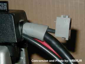
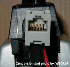
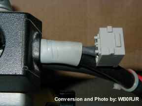
A programming cable connection can be as simple as a RJ-45 connector with "pig-tail" wires. Solder the RJ-45 wires to the bottom of the Personality Board (pin locator) and put it on the other side. It is not convenient because you have to remove the bottom of the radio (the mounting tray and 4 screws are removed) to program it. As an alternative, you can solder a RJ-45 connector to the the radio's cable connector (pin locator) and leave it hanging out of the radio connector. Here are photos of a nicely done rendition of this cable conversion (photo1, photo2 and photo3 - the radio cable connector housing is being held in a vice). The RJ-45 with pig-tail wires is Mouser part number 154-UL641D. You may also want a new 32-83859M01 gasket after opening the J1 radio connector housing. Seal the RJ-45 connector up with tape to protect it from moisture and dirt when you are not using it. For the RIB connection to a RJ-45 cable, use one of the prefabricated RJ-45 to DB-25 connectors. The last piece is a common CAT-5 patch cable. Batlabs has the programming cable pin out. Both of these RJ-45 based options are very inexpensive compared to a commercially manufactured Syntor X 9000 programming cable. One big advantage is you do not have to go through the power fuse removal, install the factory programming T-cable, reinstall the fuses, then do it all over again to remove the factory programming T-cable dance anymore.
If you make your own programming cable by attaching wires to the Personality Board or to the radio's cable connector, the wires should not be much longer than around a few inches total. If the wires are permanently attached and are too long, they can cause problems by picking up noise or even causing interference on the Systems 9000 serial bus data.
The radio systems that operate two Syntor X 9000 radios from a single Hand Held Control Head requires a special RSS, special radio firmware and special hardware (such as the SIU).
The radio systems that operates two Syntor X 9000 radios from a single Systems 9000 control head requires a special RSS, special radio firmware, special hardware and a special cable.
The Syntor X 9000 programming setup will program both the radio (RDPROG.exe) and the Systems 9000 control head (CHPROG.exe).
The Systems 9000 serial data bus is a RS-422 (with a busy line added) type of protocol which is implemented as a differential, bidirectional, serial communication bus with a single bidirectional busy line at 9600 baud (4 wires total, BUS +, BUS -, BUSY and Ground). The Radio Interface Box (RIB) converts the RS-422 and busy line into commonly available RS-232 levels used by the programming computer that runs the RSS.
Do not be fooled by the Systems 9000 label on a HCN1032 model control head. Its serial data bus is limited to the trunking Syntor X 9000 radio only and is not compatible with any conventional Syntor X 9000 radios or any other Systems 9000 radio.
All of the options (Securenet, MDC, Single Tone, Siren/PA, VRS, etc.), radio, control head and RSS RIB communicate with each other through a common Systems 9000 serial data bus. This is how a radio code plug programmed with an option can notice when the option is physically missing and get the control head to display an error message about the missing option (i.e. such as 08/10 when the Siren/PA is programmed, but the Siren/PA unit is missing). Also when the microphone PTT (which is connected to the control head) is pressed, the control head generates a serial data command to transmit and sends it to the radio (i.e. there is no physical Push To Talk wire connected between the control head and radio). These radios are really a network of microprocessors all talking to each other on a Systems 9000 serial data bus.
The radio has an internal EEPROM (this is with two Es) chip located at U502 on the Personality Board. This chip can be a 2 kilobyte 24 pin chip or an 8 kilobyte 28 pin chip. The 8 kilobyte chip is also know as an option W930. The 2 kilobyte chip will allow the radio to only program 32 modes maximum and some options will not work with this small chip. The 8 kilobyte chip will allow the radio to have up to 255 modes, depending on the RSS used to program the radio and it supports all available options. The U502 chip stores the code plug that is programmed with the RSS. U502 is socketed and can be upgraded. A 32 kilobyte EEPROM chip can be directly substituted for the 8 kilobyte chip, but only 8 k of the 32 k chip can be used. So, the 32 k and 8 k chips will both be referred to as 8 k W930 chips since they work exactly the same way in the radio.
The radio also has an internal ultra-violet erasable EPROM (this is with one E) chip located at U501 on the Personality Board. This chip holds the radios program (also called the firmware) that actually runs the radio using the RSS information you programed. The RSS can not program this chip, it can only be programmed with an external EPROM programmer. There are old and newer versions of U501 (01-80754T53 is the most recent version). Just like any program the newer versions had bug fixes and/or enhancements added. There are also U501 chips for special purpose radios (i.e. single control head dual radio drawer systems, 128 mode non-priority scan radios, a special Spectra receiver / Syntor X 9000 dual radio setup and an Advanced Securenet Board internal radio installation). All of the special purpose radios also require the 8 kilobyte W930 U502 chip. U501 is socketed and can be upgraded.
Think of the U501 firmware as the radio's operating system and the U502 code plug is a program that is run by this operating system. When you use the RSS to read or write the radio, everything is coming from or going to U502.
The control head is just like the radio, except the chips have different locations, part designations and the firmware is stored in a PROM instead of an EPROM.
Depending on the control head model, the EEPROM code plug chip is located at U2 or U0005. Just like the radio, this chip can be 2 kilobytes or 8 kilobytes and the 8 kilobyte chip is the only one that supports more than 32 modes and all available options. U2 is socketed and can be upgraded. The U005 part is soldered in and the 8 kilobyte chip is standard, except for model HCN1062 which is the only one with the 2 kilobyte U0005 chip.
Depending on the control head model, the PROM firmware is located inside the microprocessor at U1 or in the chip at U0007. Since the U1 microprocessor was factory programmed and is no longer available, this part is not practical to upgrade (i.e. you are usually stuck with what is already there). U0007 is a Motorola factory programmed ATMEL 27C256R-20JI PLCC chip, is socketed and can be changed. The last time I checked, Motorola does not make the U0007 firmware available unless you send a complete radio into the depot for repair and the control head happens to need new firmware during the repair process. Special control head firmware was and is still only available in factory supplied models with a SPnn suffix (nn is two numeric digits) or some special no longer available upgrade kits.
The same radio "operating system" analogy applies to the control head and the RSS only reads or writes to U2 or U0005.
All of these chips have an impact on the programming and operation of the radio and control head, so it can be important to know about these chips if your radio is more than a basic 32 mode radio without any options. As far as the options go, having the large W930 EEPROM in the radio and control head is the safest bet (not all options require it, but none of them exclude W930). The factory manuals indicate what is needed in the radio and/or control head for what options (Securenet, MDC, Single Tone, Siren/PA, VRS, etc.). I also have pointed out some options that do require W930 and/or special radio U501 firmware chips elsewhere.
Keep in mind that the options (Securenet, MDC, Single Tone, Siren/PA, VRS, etc.) all have their own firmware with their own part numbers (it is usually the option's microprocessor part number). Do not confuse these option firmware part numbers with radio U501 or control head U1/U0007 firmware part numbers.
This section covers some common programming problems. Nowadays some Motorola shops do not even know or remember how to program these radios. The term button or buttons will be used to refer to the control head and the term key or keys will be used to refer to the programming computer keyboard. The term mode is used instead of channel. This section was compiled with information from many different people. It is only intended to provide supplemental information on some specific programming issues, not to replace any of the Motorola documentation or training materials. Sometimes additional information is provided because problems not specifically related to programming can affect the programming process and/or can be mistaken for programming problems.
For totally reliable Syntor X 9000 RSS operation, a 286 or 386 computer no faster then 8 MHz is recommended. Most of the time, a 386 at 20 MHz is OK, sometimes a 486 SX 20 MHz with BIOS caching disabled will work, but NEVER WITH TOTAL RELIABLY. Disabling the computer's BIOS caching is a technique for slowing the computer down that may help, unless the computer is just too fast to begin with. It is simple, the faster the computer the less reliable the RSS becomes. Marginally too fast computer induced failures are characterized by it mostly working, but failing to do certain functions (the type of failures vary, see next paragraph). Faster computers can give false "SERIAL BUS FAILURE" or other messages. If you really pump up the computer speed (i.e. 333 MHz PII) it will not even run at all. The older the conventional RSS version is, the more sensitive it is to the computer's speed (i.e. some very early versions of the RSS will not even run on a 386 at 20 MHz).
One type of computer speed related problem was experienced with a 386SX at 40 MHz. It programmed the Syntor X 9000 radio, control head, DTMF option, VRS and Siren/PA just fine and had always worked with other models of Motorola radios. However, a Syntor X 9000 MDC-1200 board would program and then fail to verify. The MDC-1200 board was suspected of being bad until a slower computer was tried and then it programmed and verified correctly. The entire variety of speed related failures would be impossible to identify and the point of this paragraph is to make clear that just because things appear to be working with a faster than recommended computer, it is no guarantee it is working reliably.
A service shop should stick with an 8 MHz computer or slower for the Syntor X 9000 radios. This way they will know that any programming failures are not their computers fault and will not waste time trouble shooting the radio's hardware because of incorrect error reports caused by a slightly too fast computer. Some computers let you select the computer speed in the BIOS (an 8 MHz / 20 MHz selectable speed 386 machine is ideal, if you ever have a programming failure at 20 MHz just try it again at 8 MHz).
The computer must also boot and run real DOS. A Windows version of DOS or a Windows DOS box will not work correctly.
I have seen mixed reports of both success and failure when using MoSlo (I have never tried it) to compensate for a computer that is too fast. I do not know exactly what caused the reported failures (user configuration settings, not using real DOS, MoSlo problems, computer I/O timing problems or just plain erroneous reports, etc.?). MoSlo may or may not work for you. However, the correct computer type and speed does not require MoSlo and it will not have any computer speed related problems.
Motorola RSS for other model radios may or may not run with faster computers, but not the RSS for the Syntor X 9000 (at least not reliably). Nowadays there is no real reason to run with a computer that is too fast. Even the famously overpriced eBAY :-) has cheap computers of the 286 and 386 vintage.
Attaching and Using a Factory Programming Cable:
Some of these radios came with warning tags, instructing you not to plug a powered cable into the radio. The safest thing to do is, first turn off the power with the control head switch and remove the big fuse from the large red power wire. Then install the programming cable. Replace the fuse, turn the control head power switch on and prepare to program the radio. When removing the programming cable from the radio, the power should also be shut off first.
Even if you do not observe the above safety precaution, never power the radio on or off with an attached programming cable plugged into the RIB. When the programming cable is plugged into the RIB (it does not matter if the RIB is powered on or not) it shorts out the radio's microphone connection which allows the code plug EEPROMs in the radio and control head to be programmed. Powering the radio on or off in this condition may corrupt radio and/or control head code plug data. Only plug the programming cable into the RIB when actually writing or reading the code plug. The reason the RSS has such specific instructions on when to connect and disconnect the programming cable to the RIB, is to avoid the possibility of corrupting a code plug.
1) Turn off the radio's power switch.
2) Remove power to the radio cable (remove the large red wire fuse).
3) Remove the radio's control head cable at the radio (it must be unscrewed).
4) Plug the programming cable T-connector into the radio.
5) Plug the radio's control head cable into the top of the T-connector (the screw will not be long enough to screw it in).
6) Restore power to the radio cable (replace the large red wire fuse).
7) Connect the RIB to your programming computer (use the serial COM port the RSS is setup for).
8) Turn the computer, RIB and radio on.
9) Program the radio and/or control head.
Follow the RSS instructions on plugging in and unplugging the radio programming cable to the RIB.
10) When done programming, turn off the radio's power switch.
11) Remove power to the radio cable (remove the large red wire fuse).
12) Remove the radio's control head cable from the top of the T-connector.
13) Remove the programming cable T-connector from the radio.
14) Plug the radio's control head cable back into the radio and screw it in.
15) Restore power to the radio cable (replace the large red wire fuse).
16) Turn your radio on and use it.Even though the radio supplies power to the RIB through the programming cable, the RIB must have its own working independent power source. Either an AC power supply, an internal battery with a good charge or both. When doing it the wrong way, one time I actually managed to corrupt a radio's code plug as the programming cable was unplugged from the RIB.
If you have a home made programming connection attached to the radio cable, you do not need to mess with the fuse or the radio's cable to program it. It really simplifies the entire process. You still have to follow the RSS instructions on when to plug in and unplug the radio programming cable from the RIB.
If you have anything already programmed into the radio or control head that you want to preserve, use the RSS to read them and save whatever you read to the programming computers' disk. You can always start a brand new conventional code plug from scratch; so backing up is not absolutely essential like it is with some other Motorola radio models. However, having a saved copy of the code plug can save you some work.
When starting a new code plug, do not take the RSS option "2 - 1 to 32 Modes" and RSS option "8 - 33 to 64 modes W930" descriptions literally. You must have the W930 8k EEPROM installed to use RSS option "8" for the radio or control head (you can also use RSS option "2"). If you do not have the W930 8k EEPROM then you can only use RSS option "2". The misleading part is if you have the W930 8k EEPROM installed and you are programming 1 to 32 modes, you do not have to use option "2". In fact if you are programming for an option that requires the 8k EEPROM like VRS, then you must start it with RSS option "8", even if you only have 1 to 32 modes total to program.
It is strongly recommended to always use RSS option 8 when a radio or control head has the W930 8k EEPROM, no matter how many modes you actually need to program.
If you have no idea which size EEPROM you have in a radio or control head, make a short RSS option 8 one mode code plug (checkout the backup note first) and program it. If the RSS fails on the verify cycle then make a RSS option 2 one mode code plug and program it. If it only verifies with the option 2 one mode code plug then you do not have the W930 EEPROM. If the RSS fails with both option 8 and option 2 then you have a problem with whatever you were programming or your programming equipment. If it programs and verifies with RSS option 8 then it is a W930 8k EEPROM and you can now make a real RSS option 8 code plug for it. You can also open the equipment up and physically verify which size EEPROM is present. The radio is easy to check, just open the bottom of the radio and look at the chip in the 28 pin U502 socket. If it is a 24 pin chip (4 socket pins are empty) then it is a 2k EEPROM and if it is a 28 pin chip (all the socket pins are used) it is at least an 8k EEPROM. You can use the same method to check the older DIP style construction control head's U2 chip. All of the newer usable SMD type construction heads are 8k except for the HCN1062 (watch out for control heads that have had the HCN1062 part number on the back switched with another part number).
When initially programming the user modes in a new code plug from scratch, it is a good idea to first setup a sample mode with blank frequencies, but only set every individual selection you want to appear in every mode into your sample mode. Then use the "C" key Copy to ALL function to copy your sample mode to all the other modes. Now all of your modes will have a common set of selections already setup. The reason for doing this first is it will wipe out any information already programmed in all the other modes (only if you had programed anything already). This trick will save you from allot of repetitive typing as you program each mode.
Because the conventional Syntor X 9000 RSS does not give you an easy to use control that will insert a new mode or delete an existing mode, it is strongly recommended you do your homework and create a sequentially numbered complete list of all your modes first. Use a word processor or make a list by hand. Inserting or deleting a mode from an existing code plug with lots of modes in it must be done manually and is very difficult / time consuming. Just keep in mind this RSS requires more up front preparation from you than Motorola RSS programs for other radio models (there are two Syntor X 9000 RSS manuals with worksheets).
The BAND / FREQUENCY RANGE selection must match the physical tuning ranges of the radio's VCO. For example; this means if you have an unmodified range 2 VHF radio, you must select the range 2 BAND / FREQUENCY RANGE (148-172, 148-174 or 150-174). Nothing in this RSS will prevent you from making the wrong choice. After you select the BAND / FREQUENCY RANGE, any and all frequencies entered into the RSS will be permanently stuck in that frequency range. You can not read in a VHF range 1 code plug (136-154), change the BAND / FREQUENCY RANGE selection to VHF range 2 (150-174) and turn it into a range 2 code plug (it will still be a range 1 code plug, except any new frequencies entered will be range 2, creating a nasty mix of old range 1 and new range 2 frequencies in the same code plug). The rest of this section explains what will happen if you put the wrong frequency range code plug into a radio. See the radio model page for information on figuring out what your radio's frequency range is.
When you start a code plug and select a BAND / FREQUENCY RANGE, make sure you always use the exact same BAND / FREQUENCY RANGE every time you edit your saved radio code plug or read the radio. Not all RSS versions will remember your old BAND / FREQUENCY RANGE selection. As already mentioned above, if you were to enter the first 10 modes with a VHF range 1 (136-154 MHz) selection save the program and exit, then start it back up and enter 5 new modes with a VHF range 2 (150-174 MHz) selection, the first 10 modes and the 5 new modes would use totally different frequency ranges to switch the VCO sub-ranges. The first 10 mode entries will not be automatically changed to the new frequency range 2 selection. If you want a VHF range 2 code plug you will have to start a new VHF range 2 code plug from scratch.
It is recommended that you type the exact frequency range used in the RSS BAND / FREQUENCY RANGE selection into the file description when you save a code plug.
A BAND / FREQUENCY RANGE selection mistake can be hard to detect. For example; a VHF range 1 code plug entered into an unmodified VHF range 2 radio will only cause coverage gaps where the physical VCO sub-range does not match the RSS sub-range switching frequencies. This will cause some frequencies to achieve a VCO lock, some will have a marginal lock and others will not lock, creating gaps in the frequency coverage. If you are lucky and pick frequencies to program that lock, you may not notice until it gets really hot or cold out and one or more frequencies will no longer lock or until you add a new frequency to the code plug at some latter date.
If you take an unmodified range 2 VHF radio and put a range 1 code plug in it, the radio's VCO typically will not lock on frequencies around 146 to 147 MHz (this is a common HAM radio conversion mistake). This is because the RSS is telling the microprocessor to change the VCO internal frequency range when that VCO's internal frequency range is not physically able to reach frequencies from 146 to 147 MHz. The VCO is typically capable of reaching the 146 ro 147 MHz frequencies, but not on the range 2 VCO internal frequency range selected by the range 1 RSS code plug. This is what happens when the physical frequency ranges built into the VCO tuning do not match the blind assumptions the RSS makes about what frequency to to change VCO frequency ranges at (i.e. the actual VCO tuning and the RSS blind tuning assumptions are out of sync). Since the radio's microprocessor has no way to tell when the VCO is not locking, the radio and/or RSS have no way of detecting these problems much less trying to correct them.
If you modify the frequency coverage range of your VCO by changing the microstrip tuning pads, you should use the RSS range that is closest to you new VCO range and start a new code plug from scratch. There are special versions of the RSS that have special BAND / FREQUENCY RANGE selections. As far as I know Motorola does not provide these special versions any longer. You can also hack the radio EEPROM code plug itself to change the VCO sub-range switching (it uses the exact same VCO frequency V0 / V1 sub range switching bit scheme as the Syntor X radios), but you will have to figure out how to regenerate the correct U502 EEPROM checksum after your change it.
Scan Enable only applies to the control head scan on or off function for each mode in the radio. Every time you use the control head Mode button to select a mode, the Scan Enable setting for that selected mode will be in effect.
If you set the Scan Enable to OFF it will disable the scan whenever you use the control head to select a mode that is programmed this way.
If you set the Scan Enable to ON it will force the scan on whenever you use the control head to select a mode that is programmed this way.
If you set the Scan Enable to OPERATOR SELECT and you program the control head Scan button, it will allow the operator to turn the scan on or off whenever you use the control head to select a mode that is programmed this way. This does not mean you can have operator select of any individual scan modes. Enabling operator select scan modes is only done in the Scan List programming described below.
If you program the Scan button on the control head, the LED below this button will light up anytime the scan is turned on. It will even do this when the Scan Enable is set to ON and the radio operator has no control over the scan on / off function (i..e. the LED lets you know the scan is on regardless of how it was turned on). There is additional information on the control head Scan button programming in the Scan List section below (i.e. the control head Scan button is required to allow the operator to enter individual operator select scan modes, even when the Scan Enable is set to ON instead of OPERATOR SELECT).
The Scan List programming determines how the the individual modes that are going to be scanned are put into the radio's scan list and which type of scan list will be used. Every time you use the control head Mode button to select a mode and the scan is activated (i.e. the radio operator presses the control head Scan button or the scan is forced on in the RSS programming), the Scan List setting for that selected mode will be in effect.
The programming screen with the Scan List option does not display anything about how the Scan List options are configured. It only displays three asterisks (***). You must use the right arrow to select this field before you can see how the Scan List options are configured on the Scan List programming screen. Each individual mode has its own Scan List settings.
The Scan List programming screen has three different parts. The first part is the P1 priority scan mode selection, the second part is the P2 secondary priority scan mode selection and the third part is the NP LIST non-priority scan modes list selection. When you first enter the Scan List programming screen with the right arrow key you are at the P1 priority scan mode selection. After you press the 'N' key you will go to the P2 secondary priority scan mode selection. After you press the 'N' key again you will go to the NP LIST non-priority scan modes list selection and when you press the 'N' key again you will exit the Scan List programming screen. There is an exception, if the P1 priority scan is not operator select and no P1 priority mode is selected in the graphic display, the P2 secondary priority priority selection is skipped. Look in the lower left hand corner of the Scan List programming screen to see which one of the three different parts your are actually in.
While you are at any one of the three different Scan List programming screen parts, you may press the 'O' key (the letter O, not the numeric digit) and it will toggle the OPERATOR SELECT PARAMETERS at the bottom right of the screen. Depending on which part you are on, the P1, P2 or NP LIST will appear or disappear at the bottom right hand of the screen. You can experiment and press the 'O' key to see this in action. Be careful, when you toggle the operator select option on, any of those modes selected in the large graphic display will be removed and forgotten (i.e. the original modes do not reappear in the large graphic display when the operator select option is toggled back off).
Anything missing from the OPERATOR SELECT PARAMETERS at the bottom right of the screen will not be programmable from the control head buttons (i.e. P1, P2 or NP LIST). In this case the scan modes can only be programmed from the RSS and the radio operator will have no control over the individual scan modes that are selected (see mode slaved explanation). Anything present on the OPERATOR SELECT PARAMETERS at the bottom right of the screen will only be operator programmable from the control head buttons (i.e. P1, P2 or NP LIST). This is a case of either one or the other, never both at the same time. For some people this can be confusing because some Motorola RSS for other radio models (i.e. Spectra, etc.) lets you program a list of scan modes in the RSS and still have control head operator select scan modes at the same time.
You must select if each P1, P2 and NP LIST scan lists are RSS programmed or operator select for each mode (i.e. P1 can be RSS, P2 operator select and NP LIST RSS or any combination you want). For example: some people make each mode have itself as the P1 scan mode by making it RSS programmed (i.e. mode slaved). Then they make P2 and NP LIST operator select. When a mode is selected on the control head and the Scan is activated, the selected mode becomes the P1 priority scan mode and the radio operator can choose their own P2 and NP LIST scan modes.
You can also set any P1, P2 and NP LIST scan to RSS programmed, but leave the scan list empty. This can be used to selectively disable any of of these 3 scan lists for any selected mode. However, if you attempt to disable all three P1, P2 and NP LIST scan lists this way, the RSS will not let you exit the Scan List programming screen without entering at least one NP LIST scan mode. In this case you should set the Scan Enable to OFF to disable all scanning for this selected mode instead of trying to blank all three P1, P2 and NP LIST scan settings.
The Syntor X 9000 has a unique scan feature. The mode selected on the control head does not have to be included in the scan. Even though the selected mode is displayed, while the scan is active you will not hear any activity on this selected/displayed mode. This can be misleading to the radio operator and unfamiliar to technicians that program scanning into other Motorola radio models (other radios force you to include the selected mode in the scan). Of course it is not a good idea to leave the selected mode out of the scan list as the radio operator will probably assume it is being scanned and might miss something important. The radio operator could also make an erroneous report that the Syntor X 9000 radio has malfunctioned (if they do not understand how the scan list works and ran into this so called "feature").
Each individual mode is allowed to have its own unique RSS programmed scan list (i.e. each mode has its very own RSS scan list with a unique list of modes to scan), but no operator select is allowed for these RSS individual mode scan lists. The operator select modes all come from a single operator select scan list (i.e. all the operator select scan modes use a common scan list entered by the radio operator from the control head buttons). Keep in mind that when power is lost on the radio's large red and black cable leads, the radio will forget the operator select scan mode list (i.e. the operator will have to restore the scan list after power is restored and the radio is turned back on). The radio will not forget any of the RSS programmed scan lists.
Because each mode can be programmed for operator select Scan List selection or RSS Scan List selection, you can create quite a patch work of different scan mode selections in all the different radio modes. Usually one scan type (i.e. operator select scan list) or the other scan type (i.e. RSS programmed scan list) is chosen for all the radio modes to simplify the interface for the radio operator. The mode the radio operator selects with the control head buttons will pick the Scan List to be used when the scan is activated.
If the scan is set to allow operator select of the P1, P2 or NP LIST then you will need to program the Scan button on the control head, so the radio operator can enter scan modes into the operator select portion of the scan list. Even if you also program the above Scan Enable to ON in every mode, you still need to program the Scan button on the control head or the radio operator will not be able to enter scan modes into the operator select portion of the scan list.
If all the scan lists are set to never allow any operator select of the P1, P2 and NP LIST and the Scan Enable is never set to OPERATOR SELECT, or the Scan Enable is set to OFF in all the modes, then you do not need to program the Scan button on the control head.
There is a special version of Motorola factory RSS specifically for 128 mode radios. These 128 mode RSS versions are identified with a SP05 suffix. This RSS uses the "S" key to toggle the Scan List graphic display between modes 1 through 64 and modes 65 through 128. Special U501 firmware 01-06707T52 is required to scan up to 128 non-priority modes. Of course option W930 is also required in the control head and radio. There is also at least one non-factory hacked RSS that will program up to 255 modes running around out there, but its mode slaved Scan List graphic display screen only goes up to mode 64 (the operator select non-priority scanning will go as high as U501 will let it go).
As far as I know, the Syntor X 9000 and MCX 1000 are the only Motorola mobile radios to allow up to 128 scan modes at one time. For the Syntor X 9000, special Personality Board U501 firmware and special RSS is required to exceed 64 modes. The W930 8k EEPROM for the radio is also required to exceed 32 modes. If other models of Motorola radios allow any scanning at all, it is usually limited to 16 scan modes maximum at one time.
When you use the control head to select a mode and the scan is activated (i.e. the radio operator presses the control head Scan button or the scan is forced on in the RSS programming), the Scan Squelch setting from your selected mode will apply to all the scanned modes. This means if the mode you select on the control head has Scan Squelch set to CSQ, then all the modes being scanned will be in carrier squelch (CSQ) mode regardless of any mode's receive squelch programming (i.e. it will ignore any Rx PL or DPL). If the mode you select on the control head has Scan Squelch set to CODED, then all the individual modes being scanned will use their programmed receive squelch (i.e. Rx CSQ, PL or DPL). Of course the Scan Squelch setting is only used when you are scanning and has no effect at any other time.
It is a common mistake to only program modes that have RECEIVE SQUELCH TYPE PL or DPL enabled as CODED Scan Squelch and to program modes that have RECEIVE SQUELCH TYPE set to CSQ as CSQ Scan Squelch. Then if you select a mode with Scan Squelch set to CSQ and start the scan, all of the scanned modes with RECEIVE SQUELCH TYPE PL or DPL programmed will not use their receive PL or DPL. However, when you select a mode with Scan Squelch set to CODED and start the scan, all of the scanned modes with RECEIVE SQUELCH TYPE PL or DPL programmed will use their receive PL or DPL. This programming mistake can be very confusing for the radio operator.
When operating your radio to check out your code plug programming, keep in mind that if the microphone HUB is off hook (i.e. the back of the microphone is not grounded or if it has a button that is not pressed) the Rx PL/DPL will be defeated anyway. These buttons are know for going bad and the connector pins 23 & 40 may need to be checked with an ohm meter too make sure they short while pressing the button in. The control head SQL button may also be set for MONITOR ON which will also defeat the Rx PL/DPL.
Be aware that if Scan Squelch is set to CODED and the scan stops on a priority mode with RECEIVE SQUELCH TYPE PL or DPL enabled, the scan will stop. If the Rx PL or DPL does not match what is programmed for that priority mode in the code plug, the radio's audio will not unmute and the scan will remain stopped (except to periodically check the primary priority if the scan is stopped on the secondary priority) until the priority frequency is clear of received signals. If this same thing happens to a non-priority scan mode instead of a priority scan mode, the radio will not unmute and the scanning will simply resume (i.e. it will not remain stopped).
Most of the time you should just decide which type of Scan Squelch you want to use (i.e. CSQ or CODED) and set it exactly the same way in all your modes. This will make using the scan allot less confusing for the radio operator.
This is just a reminder to set the Radio Programming screen SCAN RECEIVE HANG TIME and SCAN TRANSMIT HANG TIME to a reasonable delay whenever you program Talkback Scan into any mode. The default hang times are way too short to allow the radio operator to actually use Talkback Scan. Somewhere around 4 seconds or longer is a typical hang time. If you do not want any hang times to be slowing down the resumption of the scan (after activity ceases on a mode the scan had stopped on), then Talkback Scan should not be programmed into any mode.
The Syntor X 9000 Talkback Scan has one thing that is different from other radios. You can program a "TbScn" Indicator Button button on the control head and set Talkback Scan for operator on/off select in the radio's individual mode programming. Other radios usually do not allow control head operator select.
Some other Motorola radios like Spectra have a Scan Off HUB selection. When enabled, it causes the scan to stop when the microphone is removed from its HUB. Scan Off HUB programming is not available on the Syntor X 9000.
Programing Talkback Scan is the next best alternative. Making use of the secondary priority mode dynamic priority scan (found on the Radio Programming screen) can enhance Talkback scan operation. When you are scanning and you hear something you want to respond to, press the control head Sel button and make the scan mode you are listening to the secondary priority mode. This will allow the radio receiver to easily recapture this mode if there is a long enough pause for the scan to resume. Of course you should not program the primary priority scan mode when using this technique, as it can tear you away from the middle of a secondary priority mode Talkback scan conversation quite unexpectedly.
The low band radios (29 to 54 MHz) are the only ones that use a special receiver noise canceling system called an Extender, which is entirely built into the low band radio drawer. The Extender is a sophisticated noise canceling system that outperforms the simple noise blanker found in other low band radios. The Extender design has also been used in Mocom 70, Mitrek and Syntor X radios (possibly others models I am not aware of). The Extender is standard equipment in every Syntor X and Syntor X 9000 low band radio.
Each mode can have the Extender set to NO, YES or OPERATOR SELECT. If you are not programming a low band radio, this option will be shown as N/A (Not Available).
When a mode has the Extender set to NO, the Extender will be OFF, whenever you use the control head to select a mode that is programmed this way.
When a mode has the Extender set to YES, the Extender will be ON, whenever you use the control head to select a mode that is programmed this way.
When it is set to OPERATOR SELECT, the control head Indicator Ext button is used to turn the Extender ON or OFF, whenever you use the control head to select a mode that is programmed this way.
When the control head Ext button is programmed, the LED below this button will always show the ON/OFF state of the Extender (i.e. it is lit up when the extender is ON). The LED works, even when modes with the Extender programmed as NO or YES are selected
The Extender is physically tuned for a particular frequency range. The Motorola low band service manual has the tuning instructions.
GE uses the term Extender for their vehicle repeater system, so do not confuse it with Motorola's Extender.
If the DTMF HLN5146A internal option board has internal firmware version lower than 2.0, it will always use "AND MUTING" no matter what you select with the RSS. This means for every mode that has DTMF UNIT CALL or TELEPHONE INTERCONNECT enabled, the receiver will have to receive the DTMF group code before the receiver un-mutes. I do not know how to identify the different firmware versions at this time. DTMF board firmware part numbers 01-06707T96 and 01-80748T73 are version 2.0 or higher, so "AND MUTING" programming works correctly in the RSS.
Also, the 01-80748T73 firmware will cause the radio speaker to ring like a telephone when it decodes the DTMF "Unit ID" programmed into the radio. The 01-06707T96 firmware uses "Horn and Lights" programming to send an alert when it decodes the DTMF "Unit ID".
The firmware is built into the 40 pin U4 microprocessor chip. Does anyone else have other DTMF firmware part numbers to share (I would really like to identify firmware versions lower then 2.0)?
The MDC-1200 HLN5317A internal option board requires one of two plug in daughter boards (HLN5318A or HLN5418A). The daughter boards contain memory chips used by the HLN5317A board (including the firmware for the HLN5317A MDC-1200 microprocessor). The HLN5318A daughter board is for regular MDC-1200 (option codes W370, W412, W814 or W941). The HLN5418A daughter board is for MDC-1200 Smart Status (option codes W735 or W738). Smart Status allows certain MDC codes to be time stamped, however Unit Page and Selective Call will only be allowed to decode (mobile radio page and call encode is disabled with Smart Status, only the MDC-1200 Smart Status dispatch console can encode these).
There is also a newer version of the HLN5317A that looks the same as the previous version, except it has no connector for the daughter board and therefore no daughter board either. The U7 PROM on these is typically in a PLCC socket. The part number tag on U7 identifies which version of MDC-1200 the board supports. U7 part 55T29 is supposed to be the equivalent replacement for a HLN5318B.
Both the radio drawer and control head require the 8k U502 EEPROM (option code W930) for MDC-1200 programming and operation. The conventional Syntor X 9000 MDC-1200 board should only be installed inside the radio drawer. It should not be installed inside a Siren/PA or External Options housing (this is because the J301 socket pin 15 Xtal Shift, is only available inside the radio drawer). In its trunking configuration, the trunking Syntor X 9000E MDC-1200 board does not have this placement restriction (the 9000E board shifts its own crystal frequency without using any J301 pins).
For the older DIP control heads, there is a new control head U1 microprocessor with upgraded firmware provided with the MDC-1200 field retrofit kit (this kit is NLA). The new firmware is required for all of the MDC-1200 functions to operate correctly (i.e. if you have the old control head firmware, you may not need the upgraded firmware for some basic MDC-1200 operations).
As noted in the above RSS Programming Computer Speed example, MDC-1200 programming can be very sensitive to the RSS computer type and speed. If your computer does not meet the requirements, then do not be surprised if you get strange error messages when trying to program MDC-1200. The error or fail messages may not even be the ones that start with 0A/ on the display, like you would expect. The wrong computer type will not always report the correct errors.
The control head keypad is divided into Keypad Buttons (the 1-9, RCL, SQL and DEL buttons) and Indicator Buttons (the 6 buttons over the display). The EXRD (external radio) must be programmed on a Keypad Button for a Siren/PA option. The EXRD must be programmed on an Indicator Button for the Public Address only option.
I have not seen any RSS software yet for programming a Siren/PA DEK on a Syntor X 9000.
If you setup and program a Siren/PA or Public Address and then get a 08/10 error when you power up the radio, it means either JU8 is installed in the Siren/PA (JU8 is near the large 40 pin U7 microprocessor chip under the shield), the Siren/PA cable has problems or the Siren/PA is not working correctly. If the Siren/PA board JU8 is installed, remove it and try powering up the radio again. Jumper JU8 is only used in the dual radio drawer with a single control head setup.
Checkout the HLN1185 Siren/PA notes for more hardware setup information.
When using the Siren/PA, the SIRN button must be turned on first before the EXRD or PA buttons will work.
If your Syntor X 9000 radio has the HLN4925 Personality Board and you have a HLN1185B or later Siren/PA with the HKN4304A cable, you will need to add a jumper to the Personality Board from the A pin to pin 12 inside the radio drawer. The Siren/PA taps into the radio's pin 12 through its T-Connector cable for some of its power.
The HLN1185 can hold one or two of the Internal Options Boards, plugged inside its Housing. The RSS programming is the same, no matter where the Internal Option Board is located. The one limitation is the HKN4246A and HKN4304A T-cables have no optional keyloader port, so the Securenet Internal Options Boards will not work inside the Siren/PA Housing.
If you setup your Siren/PA only intending to use the airhorn, watch out. I have been told that if the main power fails or goes low enough, the Siren/PA will default back out of manual mode and produce a default siren tone when you get it powered back up and turned on (even if you do not have any siren tone keys programmed).
Vehicle Repeater System (VRS):
To program the VRS you need RSS version R06.00.00 or later. Both the radio and control head must be programmed for the VRS. The radio must have the W930 optional 8k U502 EEPROM and the control head must have the W930 8k EEPROM. The radio code plug must be started from scratch with RSS option 8 (33 to 64 modes W930), even if you have less than 33 modes to program. Watchout, the RSS will let you start a radio VRS code plug with RSS option 2, but the VRS can malfunction in the field (especially when using the VRS priority resolution system). The control head RSS will not let you program the VRS button unless you started it with RSS option 8 W930. See Starting a New Code Plug for more W930 information.
The VRS has a microprocessor chip, but it has no RSS programmable storage capacity (i.e. EEPROM ). Because of this, the VRS code plug is contained inside the radio's U502 8k EEPROM, not in the VRS. This is apparently the primary reason for requiring the larger W930 8k radio and control head EEPROMs.
Enter the radio VRS programming screen and program it before you program any modes into your new code plug. Determine if you need to use the MOBILE DETECTOR option (see below) and either enable or disable it. Make sure to leave the VRS MOBILE DETECTOR option setting alone after you start entering your frequencies into the modes (i.e. if you decide to change it after you started entering the mode frequencies in the code plug, completely starting over with another new code plug is the safest thing to do).
If the VRS MOBILE DETECTOR option is set to ENABLED, it will create a hidden receive mode from every mode you enter into the RSS. You will not be able to access these modes as they are used exclusively by the VRS to check for other mobile radio activity (the VRS priority resolution scheme needs to be able to check for other mobile radios to shut down all except one main priority VRS, when multiple VRS equipped radios are near each other). Because of all these hidden Rx modes, this option will reduce the maximum number of modes you can program into the radio. The MOBILE DETECTOR is only enabled when the base stations use one frequency to transmit to all the mobiles and all the mobiles use a different frequency to transmit to the base stations. Take note, this is not the same as repeater operation, where the base and mobile radios all use the same transmit frequency and are all repeated on the same output frequency. Some radio systems give the base station direct telephone cable access to the repeater radios (i.e. remote base operation) so the bases do not transmit on a repeater input frequency and only the mobiles transmit on the input frequency, but if the radio system repeats all base and mobile radio traffic together on one common output frequency it is still considered repeater operation as far as VRS programming is concerned (i.e. set MOBILE DETECTOR to DISABLED for repeater or same frequency simplex mobile radio system operation).
Because enabling the MOBILE DETECTOR option creates a hidden receive mode for each regular mode entered, it will limit the maximum number of modes you can enter into your radio. Enabling Securenet will also limit the maximum number of modes. The actual limit is dynamic depending on several variable factors. I believe these limitations are only noticeable if you are using a hacked RSS to enter more than 128 modes.
The VRS (VRS models) frequency is crystal controlled and is not RSS programmable. To change the VRS frequency, the Tx and Rx crystals must be changed and the VRS must be realigned to the new frequency. All of the other VRS parameters are RSS programmable.
The VRS priority resolution scheme is compatible with the older PAC-RT vehicle repeater priority resolution scheme. The physical VRS and PAC-RT units themselves are not physically interchangeable, but vehicles with different vehicle repeaters (i.e. VRS or PAC-RT) can be setup to work together within the same radio system. The VRS programming will have to match the physical setup of the PAC-RT (the PAC-RT is not programmable).
Remember to perform the installation correctly. The VRS unit is usually cabled to the radio with a HKN4295 VRS cable. If you have a separate HLN1185 Siren/PA unit it is cabled from the VRS unit with a HKN4304 Siren/PA cable (i.e. the VRS unit must be first in this daisy chain). If you have a VRS/Siren/PA unit all in one combination unit then it is cabled to the radio with a HKN4304 Siren/PA cable.
If your Syntor X 9000 radio has the HLN4925 Personality Board you will need to add a jumper to the Personality Board from the A pin to pin 12 inside the radio drawer. The VRS taps into the radio's pin 12 through its T-Connector cable for the VRS power.
The factory stock VRS must cross band repeat. A VHF mobile must use a UHF VRS. A UHF mobile must use a VHF VRS. A low band or 800 MHz mobile can use either a VHF or UHF VRS. Same band repeat (i.e. VHF mobile and VHF VRS, or UHF mobile and UHF VRS) can cause the mobile transmitter to desense (i.e. blank out) the VRS receiver and leads some people believe they have RSS programming problems, when they really have the wrong VRS unit frequency range for their mobile radio. Just like the PAC units, it is possible to modify a VRS for same band repeat (see this discussion on the PAC page).
None of the dual radio RSS versions have VRS programming included and there is nothing indicated about jumpering a VRS for dual radio group addressing. There is also no way to select VRS audio connections for two different radios. My conclusion for now is the VRS can not be used in any dual radio single control head setup.
The VRS units are only intended to be used while the vehicle and its mobile radio is stationary. Turning on a VRS in a moving vehicle can cause lots of unpredictable priority resolution function problems for yourself and other VRS or PAC-RT equipped vehicles. Besides, it makes no sense at all to use the VRS when you have direct access to the mobile radio from inside the vehicle.
Believe it or not, the VRS is a very well designed package that successfully performs the extremely difficult job of operating cross band repeat in very close proximity to high power mobile radios, without bulky and expensive cavity filters! If you try and modify the VRS output power or monkey with its design, you will most probably end up with far less than satisfactory performance. The VRS was never meant to be a full long range repeater and its design prevents it from being one.
The External Options Housing holds one or two of the Internal Options Boards, plugged inside the External Options Housing. The RSS programming is the same, no matter where the Internal Option Board is located.
The one limitation is the HKN4295A T-cable has no optional keyloader port, so the Securenet Internal Options Boards will not work inside the External Options Housing.
The Systems 9000 control head dual radio setup has its own unique RSS. The System Interface Unit (SIU) box Hand Held Control Head (HHCH) dual radio setup also has its own unique RSS. The current Motorola RSS list only has the HHCH dual radio RSS listed. The SIU has its own separate RSS program. All dual radio drawers also require special U501 firmware 01-06710T70 and a W930 8K EEPROM. The Systems 9000 dual radio version control head also requires a W930 8K EEPROM and should have the factory original HCN1036ESP04 control head which has special firmware (or one the more recent SP04 control head models).
When programming single radios as dual radio drawers for the first time, program each radio individually one at a time (i.e. disconnect the other radio - use the correct power down and fuse removal procedure before disconnecting or reconnecting). The missing radio may cause some power up error codes that you should ignore. After the radios are reprogrammed as a primary and secondary radio drawers, you should not need to disconnect them for programming again. If you need to change a primary or secondary radio drawer to the other type, then you may need to reprogram it all by itself as a single radio first, then program it all by itself as a primary or secondary radio drawer. Make sure to program all options (i.e. Siren/PA, Securenet, etc.) with the dual radio RSS (see below).
Although you can reprogram dual radios as primary or secondary radios with both drawers connected together through the SIU, there is still a small chance of corrupting the EEPROM in the other radio you are not programming. For this reason, it may be best to first disconnect the radio drawer you are not going to program.
After you program a radio drawer as a dual radio, you can read an individual radio all by itself and write back to it with other RSS versions that are not for dual radios (only one radio at a time can be connected to the RIB). This technique is used to enter frequencies not available with the dual radio RSS (i.e. 53 to 54 MHz and 440 to 450 MHz coverage). Do not enable, view or reprogram any options (i.e. DTMF, Siren/PA, Securenet, etc.) when using any RSS other than the dual radio RSS. The dual radio RSS will probably not accept a radio code plug programmed with frequencies outside the dual radio RSS range (i.e. completely program all the options with dual radio RSS first, before using this trick to program frequencies the dual radio RSS can not read back from the radio). Make sure you save copies of the code plug for both the dual radio RSS and the regular RSS used to enter the out of range frequencies.
The special Dual Radio RSS programs have a feature not found in the other RSS programs. Under the RADIO PROGRAMMING SCREEN, if you press the 'O' key (the letter O, not the digit zero) you will get a SYNTHESIZER PARK FREQUENCY CHANGE/VIEW screen. This option is used if transmitting on one radio (either the primary or secondary radio drawer) causes interference with the other radio drawer receiver. Each of the two radios can have its own Synthesizer Park frequency programmed. If it is programmed, when one radio drawer transmits the other programmed radio drawer will change Rx frequency to the Synthesizer Park frequency to avoid interference to its receiver. This condition only lasts until the PTT is released. The Synthesizer Park frequency is blank by default and can be left unprogrammed if there is no interference problem. The Synthesizer Park frequency only applies to the radio's receiver.
Many of the Internal Option Boards have 3 jumper pads for zero ohm chip resistor jumpers located on the bottom solder side of the option board. They are usually labeled JU1, JU2, JU3 or alternately JU101, JU102, JU103. When installing an internal option board inside a dual radio drawer, these jumpers must be set correctly. The boards inside the primary radio should have only JU2 or JU102 jumpered. The boards inside the secondary radio should have only JU3 or JU103 jumpered. A zero ohm chip resistor is required for the jumper. When you program an installed internal option board in a dual radio drawer and get the dual radio error code for that internal option (i.e. something like a 34/10 primary radio error or 54/10 secondary radio error for the Singletone option) when you power up the radios, it means the internal option board is either not jumpered correctly or not working (remember to also check the option board ribbon cable for installation problems). Some Motorola manuals refer to these jumpers in a confusing manner as "radio system" jumpers for "RADIO GROUPS 1, 3, 5, 7", "RADIO GROUPS 2, 3, 6, 7" and "RADIO GROUPS 4, 5, 6, 7". The way to decipher radio groups is a single radio uses radio groups 0 and 1, a primary dual radio uses radio groups 2 and 3, a secondary dual radio uses radio groups 4 and 5, while groups 6 and 7 were never used at all. Radio groups 0 (no jumpers), 2 (jumper JU2) and 4 (jumper JU3) correspond to the binary base address of each radio group. There is a possibility that I have will check in the future, that the singletone encoder (not the one with MDC-600) Internal Option Board might require JU1 and JU2 in a primary dual radio, and JU1 and JU3 in a secondary dual radio. None of these 3 jumpers are installed on an option board in a single radio system.
In a dual radio system using the optional Siren/PA, it must be cabled to the primary radio drawer and the Siren/PA jumper JU8 must be installed (JU8 is near the large 40 pin U7 microprocessor chip under the shield). If you get a 28/10 error when you power up the radios, it means either JU8 is not installed, the Siren/PA cable has problems or the Siren/PA is not working correctly. If you get a 48/10 error when you power up the radios, it means you have accidentally enabled the Siren/PA option on the secondary radio drawer code plug and you need to disable it. If you get a 08/10 error when you power up the radios, it means one of radio drawers is programmed as a single radio or the Siren/PA option in the radio was somehow programmed in single radio mode (reprogram it as a dual radio with Siren/PA enabled). Siren/PA jumper JU8 is not installed in single radio systems. The External Radio (ExRd) audio will only deliver audio from the primary radio because there is no audio connection between the Siren/PA and secondary radio.
Standard VHF/UHF HHCH Securenet dual radio systems using the SIU must have the UHF radio connector plugged into the top position (RADIO 1) of the SIU and the VHF radio must be plugged into the middle connector (RADIO 2) of the SIU. If the two are reversed, you will not get any Tx modulation. The VHF Securenet box should only be programmed with and cabled to the VHF radio. The UHF Securenet box should only be programmed with and cabled to the UHF radio.
Unlike most other Motorola RSS, you can create a code plug from scratch without having to read a radio first. You can even program an 800 MHz code plug into a low band radio, but the low band radio's VCO will never be able to lock. Keep in mind this RSS gives you more freedom, but it does not protect you from yourself like the later radio models RSS does. This leaves you open to more subtle mistakes like selecting a RSS frequency range that does not match the radio's VCO frequency range. For example; if you select a RSS VHF range 1 frequency range and program it into a VHF range 2 radio the VCO will lock on some frequencies and have gaps where it will not lock between the frequencies that do lock.
You will encounter the term "mode slaved" in the RSS. For example; when a mode has a RSS programmed Scan List that the operator has no control over, that Scan List can be described as "mode slaved". This is because it is hard coded (i.e. not operator selectable) into that particular mode selection and is only available when the radio operator uses the control head to select that particular mode. Another example is Securenet equipped radios can be programmed so encryption is only available when certain modes are selected on the control head and it will not be available for any other modes (i.e. the Securenet operation is "mode slaved"). You will see this same "mode slaved" concept applied elsewhere in the RSS.
Here is a list of things to do if your conventional Syntor X 9000 radio will not program. Read through the entire section before you do anything to try and correct the problem. You might save yourself some time, dead end attempts and frustration that way. Start with the things that are most obviously wrong, then the things that are easiest for you to do, then work your way through the more difficult or expensive things until you hopefully solve the problem.
The most common problem usually encountered is the RSS computer being used is simply too fast.
Some of the remedies for the radio listed here are also useful for general troubleshooting and repair. Just ignore the parts that are specific to programming the radio and the programming equipment.
Because the RSS is not very good at consistently reporting one unique error message for one single problem (i.e. failure messages can vary for one single isolated problem), I have not made any attempt to chart programming failure messages and match them up with their potential fixes. I also do not have a complete list of all the RSS failure messages anyway. However, if the radio's control head is giving failure or error messages without any programming equipment attached to the radio, then the Motorola service manuals have specific trouble shooting and repair instructions for the different messages. Keep in mind, some error messages are caused because the optional hardware was removed from the radio and the old code plug inside the radio still has those missing options programmed (this happens with used radios fairly often). These error messages should go away after you fix your programming problems and correctly reprogram the Syntor X 9000. If the option getting the error message is still installed, then it probably needs repair. This failure and error code prefix chart can help you determine if the problem is from an option, instead of the radio or control head.
Be careful when pulling a chip from its socket. PC board traces can be accidentally damaged if you are not very careful about where you place any tools used to pry a chip out. A real chip removal tool should be the safest thing to use.
First, check to see if the radio works at all. If you turn the radio on and the control head reports a 01/90 BUS FAILURE error, you will not be able to program this radio until this problem is fixed. You could have hardware problems with the control head, the radio cable, the radio itself, the large red/black power leads or any combination of problems. If you can not get anything at all from the control head (i.e. the DIM button will not even work), it is locked in a SELF CHECK or the display is always blank then you will need to repair it before you can program the radio or control head.
Remember to turn the control head switch off (or remove its fuse) and pull the fuse on the red wire first, before removing or installing the radio's cable connector. Also follow the anti-static precautions when handling any boards or parts.
As I have already mentioned in the web site introduction, I do not have comprehensive safety warnings on this web site. I will however mention that whenever working with or around around automotive batteries, always at least wear eye protection. Automotive type batteries can possibly explode. I know of a former tow truck driver that almost lost his eye sight when a battery he was jumping unexpectedly exploded. The liquid sulfuric acid that got into his unprotected eyes caused some permanent eye sight loss and could have completely blinded him. Always treat these with the respect they deserve.
Keep in mind that volt meters draw microscopic amounts of current and many bad connections have no problem at all passing this tiny amount of current to the volt meter, but will cause excessive voltage drops when passing much larger amounts of current to the radio. When the radio is off and not drawing any current, a volt meter will not detect some types of bad connections at all. Also an ohm meter will not detect bad grounds and other problems when they are related to larger current flows through the connection. Physical inspection is usually the best option when checking power or ground connections. When using an ohm meter, simply verify that a connection exists to begin with, then take it apart and inspect it to find out if the connection is any good or not.
| Syntor X 9000 Personality Board P300 Pin Out | |
| P300 Pin # | Description |
| 1 | 9.6 Volts (powered by Switched B+ pin P300-4) |
| 2 | Switched +5 volts (powered by Switched B+ pin P300-4) |
| 3 | B- (ground) |
| 4 | Switched B+ (from control head power switch) |
| 5 | PA ENABLE (control line for RF power amplifier deck) |
| 6 | Fused A+ (from large Red and Black cable wires) |
| 7 | Spare |
| 8 | Keyed 9.4 Volts (only active while radio is transmitting) |
| 9 | Unswitched +5 Volts (powered by Fused A+ pin P300-6) |
| 10 | Optional Securenet Encryption Code Battery Backup Power |
Use a computer that is slow enough! It is possible that older U501 radio firmware may be a factor in some computer speed induced failures (i.e. the older the firmware the slower the computer needs to be), but this is only speculation on my part. This firmware chip is directly responsible for the radio communicating with the RIB and programming the U502 EEPROM which supports this possibility.
The conventional Syntor X 9000 radios use the Systems 9000 BUSY line to control communication between the radio, control head, any internal option cards, any external options and for programming with the RSS. Spectra, Spectra II and Astro Spectra mobile radios also use the Systems 9000 BUSY line. Most other Motorola radios do not use this BUSY line. You may be able to program your MaraTrac, Maxtrac, GTX mobiles, Radius mobiles, handhelds, etc., but this does not mean you can program a Syntor X 9000 with your programming hardware. These Systems 9000 radios are unique, so RSS programming success / failure comparisons between them and other radios are totally meaningless. The RIB takes the BUSY line and turns it into RS-232 handshake signals Clear To Send, Ring Indicator and Data Terminal Ready (CTS, RI and DTR) for the programming computer interface. This means you can program all kinds of Motorola radios and use a cable between the RIB and computer that does not even have these RS-232 handshake lines, without having any problems. If you have an aftermarket RIB it may not even have these essential RS-232 handshake lines built into it. Again, no problem with lots of Motorola radios. No problems that is, until you get to the Syntor X 9000 or any other Systems 9000 radio.
The Motorola RIB gets power from the Syntor X 9000 radio through the Motorola programming cable. If you only use the power from the radio to run the RIB, it can glitch as you unplug the programming cable and mess up the code plug you just programmed. The RIB still needs a fresh 9 volt battery or the external wall supply. Some aftermarket RIBs may not even use the power from the radio, and aftermarket programming cables might be missing the power wire from the radio. Low voltage on the RIB power can also affect the RS-232 levels the RIB uses to communicate with the computer and cause "SERIAL BUS FAILURE" messages.
There are known problems programming some control heads that have previously been programmed with a trunking RSS. If the radio programs and the control head will not, check out the control head page for more information. Remember, being able to program the radio means your programming equipment is working correctly, if your computer is within the recommended speed range. If your computer is faster than recommended, you could be fighting one of the unpredictable speed related failures when attempting to program the control head. There are three control heads that will never program.
Make sure your programming cable is in good shape. Be sure to follow the RSS instructions about plugging in and unplugging the programming cable from the RIB. When the programming cable is plugged into the radio and the RIB, it grounds the Microphone line which enables the control head's EEPROM and radio's EEPROM to be written to. If you power the radio on or off with the programming cable plugged into both the radio and RIB, it can corrupt your code plug inside the radio and/or control head. The RIB does not even have to be turned on or connected to the computer for this problem to occur.
Make sure you are using the correct size code plug for your radio and control head. If you throw an 8k code plug into a 2k U502 chip (32 modes or less allowed) you will get verify errors at the very least and it will not work. It will fail even if the 8k code plug only has 32 or fewer modes programmed. On the other hand a 2k code plug can go into an 8k U502 chip, but it will only use 2k of the 8k chip and will be limited to 32 modes maximum.
Also check the jumpers to make sure the EEPROM memory can be accessed. A 28 pin 8k chip with the wrong jumper setting will only be able to access 2k of the chip while you are programming it, then it will switch to an unprogrammed 2k section as soon as you unplug the programming cable (i.e. you can not program this incorrectly jumpered 8k chip with an 8k code plug, but you can program it with a 2k code plug and the radio will still not work). A 24 pin 2k chip with the wrong jumper setting will not program at all and you will get an instant RSS verify error as soon as the verify starts.
If any chips were installed upside down in their socket (with pin 1 on the chip at the wrong end of the socket) or a 24 pin chip was installed incorrectly in a 28 pin socket and the radio's large red and black leads were connected to the power or the radio was powered up, these chips may need replacement and there could possibly be other damage.
I received one 8k HCN1033 control head that was actually "repaired" by simply correcting the JU4 and JU5 jumpers (it was still jumpered for 2k). I was told by the previous owner that it had a "programming" problem as if the RSS or programming equipment was at fault. This misconception highlights another problem most people have. That is they only have a single Syntor X 9000 radio to test their often untried programming equipment on. Your programming equipment might be working correctly and the radio might have problems that prevent you from figuring out what or where the problem really is.
The last thing I can think of is your programming equipment and/or Syntor X 9000 may need some repair work.
--
PL, Private Line, DPL, Digital Private Line, MPL, Talkaround, MDC-600, MDC-1200, MVS-20, Securenet, Smartnet, Privacy Plus, Trunked X2, Trunked X3, Touch Code, Quick Call II, Channel Scan, Talkback Scan, System 90, System 90*s, Systems 9000, Mocom 70, Mitrek, Micor, Spectra, Spectra II, Astro Spectra, MataTrac, Syntor, Syntor X, Syntor X 9000 and Syntor X 9000E are trademarks of Motorola Inc.