Mike Blenderman, K7IC passed in 2022. This December 2021 mirror
of his onfreq.com site was extracted from the Wayback Machine.
[SYNTOR]
[SYNTOR X] [SYNTOR
X 9000 and X 9000E] [TRUNKING
SYNTOR X and SYNTOR X 9000] [SPECTRA]
[PL] [DPL] [PAC-PL
and PAC-RT VEHICLE REPEATERS][HHCH] [PROM
PROGRAMMERS] [POWER
WIRING]
[GLOSSARY]
[WEB LINKS] [SURPLUS
PARTS GUIDE] [ITEMS FOR SALE]
[WEB SITE REVISIONS]
This page is totally under construction. Many of these cable
pin outs have not been verified and can be wrong.
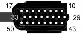
Original Style Radio Cable Pin
Out:
- Above is a front view of the cable's J5 DB-25 radio connector.
| 1 |
2 |
3 |
4 |
5 |
6 |
7 |
8 |
9 |
10 |
11 |
12 |
13 |
14 |
| 28 |
27 |
|
25 |
24 |
22 |
21 |
21 |
20 |
19 |
18 |
17
|
16 |
15 |
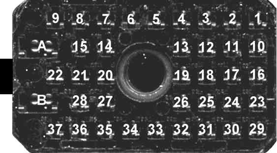
- Above is a front view of the cable's P103
control head connector pin numbers. The key to identifying the
correct physical pin out is to identify the missing pin 26.
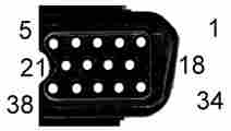
- Above is a front view of the cable's J3
DB-15 accessory connector.
3080157M01 (old part # 3080183P01) / 3080157M04 (old part # 3080183P02)
Original Style Cable Pin Out (Negative Ground) |
Radio
J5 Pin # |
Wire
Color |
Control
Head
P103 Pin # |
J3 DB-15
Pin # |
Radio Pin
Description |
| 1 |
|
|
|
PTT (Input) / SP Out 1 |
| 2 |
|
|
|
Filtered
Audio Shield / SP Out 2 |
| 3 |
|
|
|
Ignition (Output) / Securenet KID |
| 4 |
|
|
|
N.C. / Securenet Write Enable |
| 5 |
WHI |
22 |
|
Bus + (RS-422 Input/Output) |
| 6 |
|
|
|
Filtered
Audio (Output) / N.C.
HLN6055 |
| 7 |
|
|
|
Option Rx
Audio (Input) / N.C.
HLN6055 |
| 8 |
|
|
|
Option Tx
Audio (Input) / N.C.
HLN6055 |
| 9 |
BLK/BRN |
21-N.C. |
|
Detected
Audio (Output) / N.C.
HLN6055 |
| 10 |
Shield |
20-N.C. |
|
Analog Ground
/ N.C. HLN6055 |
| 11 |
Shield |
3 |
|
Mic. Low |
| 12 |
BLK/YEL |
27 |
|
Mic. Hi (Input) |
| 13 |
VIO |
|
2 |
Emergency (Input) |
| 14 |
BLK |
10 |
|
Bus - (RS-422 Input/Output) |
| 15 |
|
|
|
RSSI (Input) / Securenet Key |
| 16 |
BRN |
8 |
|
Spare 1 |
| 17 |
RED |
7 |
|
Spare 2 |
| 18 |
BLU |
6 |
|
Digital Ground |
| 19 |
BLK/ORG |
23 |
|
Reset (Input/Output) |
| 20 |
YEL |
5 |
|
A+ (Output) |
| 21 |
Shield |
24-N.C. |
|
Bus Shield |
| 22 |
BLK/GRN |
4 |
|
Switched B+ (Input) |
| 23 |
BLK/RED |
25 |
|
Busy (Input/Output) |
| 24 |
GRN |
|
6 |
Speaker Audio
Low (Output) |
| 25 |
ORG |
|
7 |
Speaker Audio
Hi (Output) |
| |
YEL |
17 |
14 |
VIP In 1 (Input) |
| |
WHT/RED |
16 |
10 |
VIP In 2 (Input) |
| |
BRN |
15 |
9 |
VIP In 3 (Input) |
| |
RED |
18 |
12 |
VIP Out 1 (Output) |
| |
BLU |
19 |
3 |
VIP Out 2 (Output) |
| |
WHT/BLU |
14 |
15 |
VIP Out 3 (Output) |
| |
WHT/ORG |
11 |
5 |
Ignition (Input) |
| |
BLK |
13 |
8 |
Digital Ground |
| |
WHT |
12 |
4 |
Switched B+ (Output) |
- The input and output notes in parenthesis are with respect to the
radio drawer, except for the J3 pins which are with respect to the
control head.
- The wires going to J103 pins 20, 21 and 24 are shown in the
schematic as broken connections at the control head end of the cable.
If pin 24 was connected to ground, it would hold the PTT active and
force the radio to continiously Tx with the later control heads.
- The notes in blue indicate the
early HLN6055 and HLN6077 Interconnect Board J5 pin outs.
- No power is carried on the Switched B+ line. It is only an
interrupt line connected to the Spectra microprocessor. The Spectra
radio drawer draws all its power through its power cable.
- RSSI stands for Receive Signal Strength Indicator. It is not
supported by this cable.
- The Ignition and VIP pins do not connect to the radio drawer and
are not available on the low/medium power radio drawer J2 connector. The radio drawer J2
connector is not normally used with these remote mount cables.
- The control head connector mates directly with the control head
circuit board pins. This connector has no other connections or
accessible pins. All the accessible connections are on the J3 DB-15 connector.
- J3 DB-15 pins 1, 11 and 13 are
not connected.
Motorcycle Radio Cable Pin Out:
- Above is a front view of the cable's J5 DB-25 radio connector.
| 1 |
2 |
3 |
4 |
5 |
6 |
7 |
8 |
9 |
10 |
11 |
12 |
13 |
14 |
| 28 |
27 |
|
25 |
24 |
22 |
21 |
21 |
20 |
19 |
18 |
17
|
16 |
15 |
- Above is a front view of the cable's P103
control head connector pin numbers. The key to identifying the
correct physical pin out is to identify the missing pin 26.
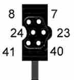
- Above is a front view of the cable's J3
DB-9 microphone connector.
HKN6062A
Motorcycle Cable Pin Out (Negative Ground) |
Radio
J5 Pin # |
Wire
Color |
Control
Head
P103 Pin # |
J3 DB-9
Pin # |
Radio Pin
Description |
| 1 |
|
|
|
SP 1 Out (Output) |
| 2 |
|
|
|
SP 2 Out - N.C. |
| 3 |
VIO |
11 |
|
Securenet KID (Input) |
| 4 |
|
|
|
Securenet Write Enable (Input) |
| 5 |
WHI |
22 |
|
Bus + (RS-422
Input/Output) |
| 6 |
|
|
|
Filtered Audio (Output) |
| 7 |
|
|
|
Option Rx Audio (Input) |
| 8 |
|
|
|
Option Tx Audio (Input) |
| 9 |
BLK/BRN |
21-N.C. |
|
Detected Audio (Output) |
| 10 |
Shield |
20-N.C. |
|
Analog Ground |
| 11 |
Shield |
|
1 |
Mic. Low |
| 12 |
BLK/YEL |
|
2 |
Mic. Hi (Input) |
| 13 |
|
|
|
Emergency (Input) |
| 14 |
BLK |
10 |
|
Bus - (RS-422
Input/Output) |
| 15 |
|
|
|
Securenet Key (Input) |
| 16 |
BRN |
8 |
|
HUB 1 |
| 17 |
RED |
14 |
|
Spare 2 |
| 18 |
BLU |
6 |
|
Digital Ground |
| 19 |
BLK/ORG |
23 |
|
Reset (Input/Output) |
| 20 |
YEL |
5 |
|
A+ (Output) |
| 21 |
Shield |
24-N.C. |
|
Bus Shield |
| 22 |
BLK/GRN |
4 |
|
Switched B+ (Input) |
| 23 |
BLK/RED |
25 |
|
Busy (Input/Output) |
| 24 |
GRN |
1 |
|
Speaker Audio Low (Output) |
| 25 |
ORG |
2 |
|
Speaker Audio Hi (Output) |
| |
YEL |
17 |
4 |
VIP In 1 - PTT 2 (Input) |
| |
GRN |
19 |
3 |
VIP Out 2 - HUB 2 (Output) |
| |
BLK |
13 |
5 |
Digital Ground |
| |
RED |
12 |
6 |
Switched B+ (Output) |
- The input and output notes in parenthesis are with respect to the
radio drawer, except for the VIP pins which are with respect to the
control head.
- The wires going to J103 pins 20, 21 and 24 are shown in the
schematic as broken connections at the control head end of the cable.
If pin 24 was connected to ground, it would hold the PTT active and
force the radio to continiously Tx with the later control heads.
- No power is carried on the Switched B+ line. It is only an
interrupt line connected to the Spectra microprocessor. The Spectra
radio drawer draws all its power through its power cable.
- RSSI stands for Receive Signal Strength Indicator. It is not
supported by this cable.
- The low/medium radio drawer J2
connector is used with this remote mount cable. The 3080010R01 accessory cable provides the radio
drawer Emergency shorting plug or button connection.
- The control head connector mates directly with the control head
circuit board pins. This connector has no other connections or
accessible pins. All the accessible connections are on the J3 DB-9 connector.
- J3 DB-9 pins 7, 8 and 9 are not
connected.
HHCH Radio Cable Pin Out:
- Above is a front view of the radio side of the cable's J5 DB-25 connector.
- Above is a front view of the HHCH side of the cable's
DB-25 connector.
- Above is a front view of the cable's J3
DB-15 accessory connector.
3080069P02
or HLN6092A (old part # 3080069P01)
HHCH Cable Pin Out (Negative Ground) |
Radio
J5 Pin # |
Wire
Color |
HHCH
Pin # |
J3 DB-15
Pin # |
Radio Pin
Description |
| 1 |
|
|
|
Data In |
| 2 |
|
|
|
On/Off |
| 3 |
|
|
|
Volume |
| 4 |
|
|
|
PTT (Input) |
| 5 |
|
|
14 |
Bus + (RS-422
Input/Output) |
| 6 |
|
|
|
Data Out |
| 7 |
|
|
|
Clock |
| 8 |
|
|
1 |
Option Tx Audio (Input) |
| 9 |
|
|
11 |
Detected Audio (Output) |
| 10 |
|
|
|
+5 Volts |
| 11 |
|
|
|
Mic. Low |
| 12 |
|
|
|
Mic. Hi (Input) |
| 13 |
|
|
2 |
Emergency (Input) |
| 14 |
|
|
10 |
Bus - (RS-422
Input/Output) |
| 15 |
|
|
|
+5 Volts |
| 16 |
|
|
12 |
VIP Out 1 (Output) |
| 17 |
|
|
3 |
HUB |
| 18 |
|
|
8 |
Digital Ground |
| 19 |
|
|
|
Load/Shift |
| 20 |
|
|
6 |
Speaker Audio Hi (Output) |
| 21 |
|
|
5 |
Ignition (Output) |
| 22 |
|
|
4 |
Switched B+ (Input) |
| 23 |
|
|
9 |
Busy (Input/Output) |
| 24 |
|
|
6 |
Speaker Audio Low (Output) |
| 25 |
|
|
|
A+ |
- I do not have any information for the yellow highlighted area.
- The input and output notes in parenthesis are with respect to the
radio drawer, except for the VIP pins which are with respect to the
control head.
- Some radio Interconnect Board
schematics refer to J5 as J1 instead and others only
refer to J5. The J5 designation is used here.
- The low/medium radio drawer J2
connector is not normally used with these remote mount cables.
- No power is carried on the Switched B+ line. It is only an
interrupt line connected to the Spectra microprocessor. The Spectra
radio drawer draws all its power through its power cable.
- J3 DB-15 pins 1, 11, 13 and 15
are not connected.
Accessory Cable Pin Out:
- Above is a front view of the cable's DB-15 accessory connector.
3080091M01
Accessory Cable Pin Out (Negative Ground)
|
J2 & J3
DB-15
Pin # |
J2 Radio Pin Description |
J3 Control Head Cable Pin Description |
| 1 |
Tx Audio or
Reset in SP applications |
No Connection |
| 2 |
Emergency (jumper
to pin 8) |
Emergency (jumper
to pin 8) |
| 3 |
VIP Out 2 *
Voice Inhibit in SP applications |
VIP Out 2 |
| 4 |
Switched B+ |
Switched B+ |
| 5 |
Ignition * (4 amp fuse attached to wire)
Switched B+ in SP customer applications |
Ignition (4
amp fuse attached to wire) |
| 6 |
Speaker Hi (speaker connector housing) |
Speaker Hi (speaker connector housing) |
| 7 |
Speaker Lo (speaker connector housing) |
Speaker Lo (speaker connector housing) |
| 8 |
Digital Ground (jumper to pin 2) |
Digital Ground (jumper to pin 2) |
| 9 |
Systems 9000
Busy |
VIP In 3 |
| 10 |
Systems 9000
BUS - |
VIP In 2 |
| 11 |
Det. Audio or
Voice Inhibit in SP applications |
No Connection |
| 12 |
VIP Out 1 *
Data Inhibit in SP applications |
VIP Out 1 |
| 13 |
Inverted PTT or
Switched B+ in SP applications |
No Connection |
| 14 |
Systems 9000
BUS + |
VIP In 1 |
| 15 |
Microphone Hi
Ground or Reset in SP applications |
VIP Out 3 |
- The grayed out pins do not have a pin installed in the DB-15
connector housing.
- The radio drawer J2 connector is normally used on a low/medium
power dash mount radio.
- The radio cable J3 connector is normally used on a low/medium
power remote mount radio.
- * - dash mount only, not connected in remote mount radio drawer
- If your radio uses the accessory plug, the radio
will not work if the above Emergency jumper is not
installed or the optional Emergency button wiring is missing and
the radio drawer command board has JU502 installed.
- If your radio uses the accessory plug, the radio
will not work if the above Emergency jumper is installed
and the radio drawer command board has JU502 removed.
- This cable provides a radio drawer Emergency shorting wire, or
the shorting wire can be replaced with Emergency button wiring.
- The accessory cable works on either J2 or J3, as shipped from the
factory. The uninstalled DB-15 male pins can be added and wired for the
J2 position, J3 position or for a low/medium power J2 programming
cable.
Motorcycle Accessory Cable Pin
Out:
- Above is a front view of the cable's J2
DB-15 accessory connector.
3080010R01
Motorcycle Accessory Cable Pin Out (Negative Ground)
|
J2 DB-15
Pin # |
Options
Pin # |
J200
Headset
Pin # |
J2 Radio Pin Description |
| 1 |
|
|
Tx Audio in
SP customer applications |
| 2 |
1 |
|
Emergency (options
plug with shorting wire) |
| 3 |
3 |
|
Horn / Lights |
| 4 |
4 |
|
Switched B+ |
| 5 |
|
|
Ignition (4
amp fuse attached to wire) |
| 6 |
|
1 |
Speaker Hi (speaker connector housing) |
| 7 |
|
2 |
Speaker Lo (speaker connector housing) |
| 8 |
2 |
3 |
Digital Ground |
| 9 |
|
|
Systems 9000
Busy |
| 10 |
|
|
Systems 9000
BUS - |
| 11 |
|
|
Detected
Audio in SP customer applications |
| 12 |
|
4 |
Hang-Up Box 1 (HUB 1) (J200 headset plug with shorting wire) |
| 13 |
|
5 |
PTT 1 |
| 14 |
|
|
Systems 9000
BUS + |
| 15 |
|
6 |
Microphone Hi |
- The grayed out J2 pins do not have a pin installed in the DB-15
connector housing.
- The options connector has a mating plug with an Emergency
shorting wire (pins 1 and 2 are shorted). The mating plug Emergency
shorting wire can be replaced with emergency switch wiring and/or
Horn/Lights relay wiring can be added.
- J200 is a headset connector. There is a mating plug with HUB 1
shorted to ground (pins 3 and 4 are shorted). An optional handlebar
mounted PTT / HUB accessory with a break away headset jack connector is
available (it replaces the mating plug with the HUB shorting wire).
Systems 9000 Radio Cable Pin
Out:
- Above is a front view of the cable's J5 DB-25 radio connector.
- Above is a front view of the cable's control head connector with
pin numbers. Each of the three horizontal rows of pins is numbered
sequentially from right to left. The cable is on the left side of the
connector.
HKN4355 / HKN4356
Systems 9000 Cable Pin Out (Negative Ground) |
Radio
J5 Pin # |
Wire
Color |
Control Head
J1 / P100
Pin # |
Radio Pin Description |
| 1 |
BLK/GRN |
46 |
PTT (Input) / SP Out 1 |
| 2 |
|
|
Filtered
Audio Shield / SP Out 2 |
| 3 |
|
|
Ignition (Output) / Securenet KID |
| 4 |
|
|
N.C. / Securenet Write Enable |
| 5 |
WHI |
17 |
Bus + (RS-422 Input/Output) |
| 6 |
|
|
Filtered
Audio (Output) / N.C.
HLN6055 |
| 7 |
|
|
Option Rx
Audio (Input) / N.C.
HLN6055 |
| 8 |
|
|
Option Tx
Audio (Input) / N.C.
HLN6055 |
| 9 |
BLK/BRN |
45 |
Detected
Audio (Output) / N.C.
HLN6055 |
| 10 |
Shield |
16 |
Analog Ground
/ N.C. HLN6055 |
| 11 |
Shield |
13 |
Mic. Low |
| 12 |
BLK/YEL |
12 |
Mic. Hi (Input) |
| 13 |
VIO |
27 |
Emergency (Input) |
| 14 |
BLK |
50 |
Bus - (RS-422 Input/Output) |
| 15 |
|
|
RSSI (Input) / Securenet Key |
| 16 |
BRN |
28 |
Spare 1 |
| 17 |
RED |
29 |
Spare 2 |
| 18 |
BLU |
49 |
Digital Ground |
| 19 |
BLK/ORG |
26 |
Reset (Input/Output) |
| 20 |
|
|
A+ (Output) |
| 21 |
Shield |
|
Bus Shield |
| 22 |
YEL |
48 |
Switched B+ (Input) |
| 23 |
BLK/RED |
33 |
Busy (Input/Output) |
| 24 |
GRN |
11 |
Speaker Audio Low (Output) |
| 25 |
ORG |
44 |
Speaker Audio Hi (Output) |
- The input and output notes in parenthesis are with respect to the
radio drawer.
- The grayed out pins are not used.
- The notes in blue indicate the
early HLN6055 and HLN6077 Interconnect Board J5 pin outs.
- No power is carried on the Switched B+ line. It is only an
interrupt line connected to the Spectra microprocessor. The Spectra
radio drawer draws all its power through its power cable.
- RSSI stands for Receive Signal Strength Indicator. This is an
option that is available on some Spectra radios. If the options is
present, there should be a RSSI key on the control head.
- J1 Pin 27 Note: The radio drawer Emergency line J1
pin 27 is not connected inside the A9, B9, C9 or E9 control head. The
control heads may add an internal jumper wire from pin
27 to a VIP In pin (pins 4, 3 or 37).
This radio drawer Emergency line can also be taken care of by a
jumper on the Interconnect Board, Command Board or low/medium power
radio drawer J2 connector.
- P100 Pin 27 Note: The radio drawer Emergency line HLN6432 board P100 pin 27 can
be jumperd to the VIP In 2 pin 3 (this is done by default on
some versions of these boards) or jumperd to ground.
- J1 / P100 Pin 27 Note: When a VIP
In pin is used for the pin 27 radio drawer Emergency Button wiring,
that VIP In port is not RSS programmed with a VIP In Emergency
function (i.e. it is only used as a convenient place to attach the
external Emergency switch wire at the cost of consuming the use of one
of the unprogrammed VIP In port pins). The DEK VIP II pins can not
be used for the radio drawer pin 27 Emergency line (the VIP II pins can
be used for the RSS programmed Emergency function).
- The low/medium radio drawer J2
connector is not normally used with these remote mount cables.
Systems 9000 Control Head to
Microphone Pin Out:
- Above is a front view of the microphone control head connector
with pin numbers. The microphone cord is hanging down below the
connector.
| Systems
9000 Control Head Microphone Pin Out |
Control
Head
J1 / P100
Pin # |
Control
Head P104
Pin # |
Description |
| 7 |
7 |
Mic. Low (Input)
- Black |
| 8 |
8 |
Mic. Hi (Input)
- Red |
|
| 23 |
5 |
PTT/HUB Reference (Input) - White |
| 24 |
6 |
PTT (Input)
- Green |
|
| 40 |
3 |
Hang Up Box (HUB) (Input) - Blue |
| 41 |
4 |
Switched B+ (Output) - Yellow |
- The input and output notes in parenthesis are with respect to the
control head.
- The colors shown are for the cable wires inside the microphone
housing. Most microphone cables do not have the yellow Switched B+
wire.
- The P104 pin numbers are for
the alternate B2, C2, E2, A4, A5, A7, B4, B5, B7, C4, C5, C7, E4, E5
and E7 control head front microphone connectors. However, the
microphone schematics still use the J1 pin numbers, so the P104 pin
numbers are not shown on the above connector pin out drawing.
- The newer SMD control heads, like the HCN1063 and HCN1073, have
internal jumpers that can reconfigure some of the control head J1 pins such that the descriptions above
would no longer be correct for those control head pins. Other models of
control heads should be checked for physical modifications (i.e. cut PC
traces, wire jumpers and extra components soldered point to point on
the PC board) that can have the same effect on the description. Expect
to find modifications on control heads with a kit number below the
model number.
- One reconfiguration example is the control head pin 41 can be
changed from Switched B+ to Speaker Audio Hi. This
could be done for a telephone style handset.
Systems 9000 Control Head to
VIP Pin Out:
- Above is a front view of the Vehicle Interface Port (VIP) control
head connector with pin numbers. Each of the three horizontal rows of
pins is numbered sequentially from right to left.
| Systems 9000 Control Head to Vehicle Interface Port Pin Out |
Control
Head
J1
Pin # |
Description |
| 1 |
VIP Out 2 (Output) |
| 2 |
VIP Out 1 (Output) |
| 3 |
VIP In 2 (Input) |
| 4 |
VIP In 1 (Input) |
| 5 |
DEK Data Out (Output) |
|
| 18 |
Switched B+ (Output) |
| 19 |
Switched B+ (Output) |
| 20 |
DIGITAL GROUND |
| 21 |
DIGITAL GROUND |
|
| 34 |
VIP Out 3 (Output)
/ DEK Strobe (Output) |
| 35 |
Switched B+ (Output) |
| 36 |
DIGITAL GROUND |
| 37 |
VIP In 3 (Input)
/ DEK Data In (Input) |
| 38 |
DEK Clock (Output) |
HLN6432 Systems 9000
Control Head to
Vehicle Interface Port Pin Out |
Control
Head
P100
Pin # |
Description |
| 1 |
VIP Out 2 (Output)
/ DEK Data Out (Output) |
| 2 |
VIP Out 1 (Output)
/ DEK Clock (Output) |
| 3 |
VIP In 2 (Input)
/ Optional Radio Drawer Emergency Jumper |
| 4 |
VIP In 1 (Input) |
| 5 |
Jumper
to P100 pin 1 - DEK Data Out (Output) |
|
| 18 |
Switched B+ (Output) |
| 19 |
Switched B+ (Output) |
| 20 |
DIGITAL GROUND |
| 21 |
DIGITAL GROUND |
|
| 34 |
VIP Out 3 (Output)
/ DEK Strobe (Output) |
| 35 |
Switched B+ (Output) |
| 36 |
DIGITAL GROUND |
| 37 |
VIP In 3 (Input)
/ DEK Data In (Input) |
| 38 |
Jumper
to P100 pin 2 - DEK Clock (Output) |
- The input and output notes in parenthesis are with respect to the
control head.
- The first table "Systems 9000 Control Head to Vehicle
Interface Port Pin Out" is for the A9, B9, C9 and E9 control heads.
- The second table "HLN6432
Systems 9000 Control Head to Vehicle Interface Port Pin Out" is for
the A4, A5, A7, B4, B5, B7, C4, C5, C7, E4, E5 and E7 control heads using the HLN6432 board
and the Systems 9000 cables. An enhanced control head circuit
board is required to make use of the DEK pins.
- When a DEK is programmed into the radio's code plug, the control
head VIP port is used as a DEK Expansion port, which automatically
changes pins 34 and 37 to support the DEK. In addition, the A4, A5, A7,
B4, B5, B7, C4, C5, C7, E4, E5 and E7 control
heads change pins 1 and 2 (see below).
- The A9, B9, C9 and E9 control heads have internal jumpers that
can reconfigure some of the control head pins such that the
descriptions above would no longer be correct for those control head
pins. Other models of control heads should be checked for physical
modifications (i.e. cut PC traces, wire jumpers and extra components
soldered point to point on the PC board) that can have the same effect
on the description. Expect to find modifications on control heads with
a kit number below the model number.
- The A4, A5, A7, B4, B5, B7, C4, C5, C7, E4, E5 and E7 control
heads are missing two outputs found on the A9, B9, C9 and E9 control
heads. They are the DEK Clock and DEK Data Out pins that are used to
connect a DEK to the control head. The enhanced control head has built-in improved
firmware that allows it use VIP Out 1 and VIP Out 2 to support the
DEK. In addition, the HLN6432 board
provides the wiring changes to allow this to take place.
- The HLN6432 board has a
jumper to connect the radio drawer Emergency line to VIP In 2. If the
VIP In 2 pin is used as the optional Emergency button connection, VIP
In 2 is not programmed to do anything in the RSS. Some revisions of
this board also have a jumper to ground the radio drawer Emergency
line. This optional radio drawer Emergency pin will not work when used
with a Physical Security Housing.
Sytems 9000 Direct Entry Keyboard
(DEK) Cable Pin Out:
- Above is a front view of the Vehicle Interface Port (VIP) control
head connector with pin numbers (it can also be the DEK Expansion
connector). Each of the three horizontal rows of pins is numbered
sequentially from right to left. The cable is not shown as it comes
straight out of the back of the connector.
- Above is a front view of the DEK connector with pin numbers. The
cable is hanging down below the connector.
| Systems 9000 DEK Cable Pin Out |
Control
Head VIP J1 / P100
/ DEK J1
Pin # |
DEK J1
Pin # |
DEK
Description - VIP Description |
| 1 |
|
N.C. |
| 2 |
|
N.C. |
| 3 |
|
N.C. (Optional Radio
Drawer Emergency Pin) |
| 4 |
|
N.C. |
| 5 |
40 |
DEK Data Out (5 Output, 40 Input) |
|
| 18 |
|
N.C. |
| 19 |
|
N.C. |
| 20 |
|
N.C. |
| 21 |
|
N.C. |
|
| 34 |
24 |
DEK Strobe (34 Output, 24 Input) VIP
Out 3 |
| 35 |
41 |
Switched B+ (Input) |
| 36 |
7 |
Ground |
| 37 |
8 |
DEK Data In (37 Input, 8 Output) VIP
In 3 |
| 38 |
23 |
DEK Clock (38
Output, 23 Input) |
- The input and output notes in parenthesis are with respect to a
DEK.
- When using the HLN6432
Systems 9000 Converter board, DEK Data Out is tied to the control head
VIP Out 2 and DEK Clock is tied to the control head VIP Out 1.
- The large connector on the back of the DEK looks like a Systems 9000 control
head connector. In reality, the DEK connector pins that would appear to
be Systems 9000 microphone pins are in fact the DEK expansion input
pins, the pins that would appear to be Systems 9000 VIP pins are in
fact connections for another DEK (i.e. the DEK expansion output pins)
and the pins that would appear to be Systems 9000 Control Head
Connection pins are in fact VIP II pins (see below).
- When a DEK is connected to a control head, the DEK cable (larger
cable connector) is connected to the control head J1 / P100 VIP port (pins listed above)
and to the J1 DEK connector (smaller
cable connector) where it looks like a microphone should go (pins
listed above).
- When a DEK is connected to another DEK, the J1 DEK cable (larger cable connector) is
connected to the DEK expansion port (pins listed above) and to the
second J1 DEK connector (smaller cable
connector) where it looks like a microphone should go (pins listed
above).
- From the table above, it would appear the DEK uses VIP 3 input
and output. This is not really the case and the VIP 3 input and
output pins are moved to the VIP II pins (see below) on the DEK.
- The radio drawer Emergency button line can be connected to VIP in
2 (J1 / P100 pin 3) on the control head VIP cable connector. The
control head or HLN6432 board will
require jumpering to pin 27 to support this Emergency connection. This
Emergency pin will not work when used with a Physical Security Housing.
Systems 9000 Direct Entry Keyboard
(DEK) VIP II Pin Out:
- Above is a front view of the DEK Vehicle Interface Port (VIP) II
control head connector with pin numbers. Each of the three horizontal
rows of pins is numbered sequentially from right to left. Ignore the
cable shown in this picture, this connector (15-80212L01) does not have
a molded in cable.
| DEK Vehicle Interface Port II Pin Out |
DEK
VIP II J1
Pin # |
Description |
| 10 |
Ground |
| 11 |
Ground |
| 12 |
Ground |
| 13 |
N.C. |
| 14 |
N.C. |
| 15 |
VIP In 1 (Input) |
| 16 |
VIP In 2 (Input) |
| 17 |
VIP In 3 (Input) |
|
| 26 |
N.C. |
| 27 |
N.C. |
| 28 |
N.C. |
| 29 |
N.C. |
| 30 |
N.C. |
| 31 |
N.C. |
| 32 |
N.C. |
| 33 |
N.C. |
|
| 43 |
VIP Out 1 (Output) |
| 44 |
VIP Out 2 (Output) |
| 45 |
VIP Out 3 (Output) |
| 46 |
N.C. |
| 47 |
N.C. |
| 48 |
Switched B+ (Output) |
| 49 |
Switched B+ (Output) |
| 50 |
Switched B+ (Output) |
- The input and output notes in parenthesis are with respect to the
DEK.
- The grayed out pins are not used.
- Because the DEK uses the control head VIP connector pins, the VIP
connection is automatically moved to the DEK (when you change the
control head RSS number of DEKs setting to be higher than zero), on the
side of the DEK connector that looks like it would normally
have been used for a Systems 9000 Control Head to Radio connection.
This relocated VIP connector was renamed the VIP II connection.
- The first DEK replaces the VIP connections (on its VIP II
connector) that used to come from the Systems 9000 control head. A
second DEK adds another complete set of VIP pins on its VIP II
connector. The control head RSS is used to program these pins.
- The VIP II connector housing could be used for a "roll your own"
radio cable connector and plugged into a Systems 9000 control head
instead of a DEK.
- If you add two DEK's to a control head, each DEK has its own VIP
II connector, giving you a total of 6 VIP input pins and 6 VIP output
pins. The functions for all these pins are programmed by the control
head RSS.
Spectra Radio to Securenet Physical
Security Housing Cable Pin Out:
- Above is a front view of the cable's J5 DB-25 radio connector with pin
numbers.
| 1 |
2 |
3 |
4 |
5 |
6 |
7 |
8 |
9 |
10 |
11 |
12 |
13 |
14 |
15 |
16 |
17 |
18 |
19 |
20 |
21 |
22 |
23 |
24 |
- Above is a front view of the cable's J2 / J5 Physical Security
Housing connector pin numbers.
Spectra to Physical Security Housing
HKN6034A / HKN6035A
Cable Pin Out (Negative Ground) |
Radio
J5 Pin # |
Wire
Color |
Housing
J2 / J5
Pin # |
Radio Pin Description |
| 1 |
|
|
PTT (Input) / SP Out 1 |
| 2 |
|
|
Filtered
Audio Shield / SP Out 2 |
| 3 |
|
|
Ignition (Output) / Securenet KID |
| 4 |
|
|
N.C. / Securenet Write Enable |
| 5 |
WHI |
7 |
Bus + (RS-422 Input/Output) |
| 6 |
|
|
Filtered Audio (Output) |
| 7 |
BLK/BLU |
3 |
Option Rx Audio (Input) |
| 8 |
BLK/GRN |
19 |
Option Tx Audio (Input) |
| 9 |
BLK/BRN |
18 |
Detected Audio (Output) |
| 10 |
Shield |
17 |
Analog Ground |
| 11 |
Shield |
10 |
Mic. Low |
| 12 |
BLK/YEL |
4 |
Mic. Hi (Input) |
| 13 |
VIO |
22 |
Emergency (Input) (see note) |
| 14 |
BLK |
8 |
Bus - (RS-422 Input/Output) |
| 15 |
|
|
RSSI (Input) / Securenet Key |
| 16 |
|
|
Spare 1 |
| 17 |
|
|
Spare 2 |
| 18 |
BLU/Shield |
9, 24 |
Digital Ground |
| 19 |
WHT/RED |
5 |
Reset (Input/Output) |
| 20 |
YEL |
1 |
A+ (Output) |
| 21 |
Shield |
11, 20 |
Bus Shield |
| 22 |
RED |
6 |
Switched B+ (Input) |
| 23 |
BLK/RED |
21 |
Busy (Input/Output) |
| 24 |
GRN |
12 |
Speaker Audio Low (Output) |
| 25 |
ORG |
13 |
Speaker Audio Hi (Output) |
- The input and output notes in parenthesis are with respect to the
radio.
- The notes in blue indicate the
HLN6077 Interconnect Board J5 pin outs.
- This cable goes from the Spectra radio to the 24 pin Securenet
Physical Security Housing connector.
- The grayed out pins are not used.
- The low/medium radio drawer J2
connector is not normally used with these remote mount cables.
- The radio drawer Emergency line can have a custom wire
added from the Physical Security Housing pin 22 for an optional
external Emergency button.
- J2 / J5 Housing pins 2, 14, 15, 16 and 23 are not
connected to the J5 Radio pins.
- The early HLN6055 Interconnect Board J5 pin out will not work with the
Physical Security Housing.
- Manual reference - 6880102W55.
Original Style Control Head to
Securenet Physical Security Housing Cable Pin Out:
| 1 |
2 |
3 |
4 |
5 |
6 |
7 |
8 |
9 |
10 |
11 |
12 |
13 |
14 |
15 |
16 |
17 |
18 |
19 |
20 |
21 |
22 |
23 |
24 |
- Above is a front view of the cable's J2 / J5 Physical Security
Housing connector pin numbers.
- Above is a front view of the cable's J100 Physical Security
Housing connector pin numbers.
| 1 |
2 |
3 |
4 |
5 |
6 |
7 |
8 |
9 |
10 |
11 |
12 |
13 |
14 |
| 28 |
27 |
|
25 |
24 |
22 |
21 |
21 |
20 |
19 |
18 |
17
|
16 |
15 |
- Above is a front view of the cable's P103
control head connector pin numbers. The key to identifying the
correct physical pin out is to identify the missing pin 26.
- Above is a front view of the cable's J3
DB-15 accessory connector.
HKN6036A
/ HKN6037A Physical Security Housing to Control Head
Original Style Cable Pin Out (Negative Ground) |
Housing
J2 / J5
Pin # |
Housing
J100
Pin # |
Wire
Color |
Control
Head
P103 Pin # |
J3 DB-15
Pin # |
Pin
Description |
| 1 |
|
YEL |
5 |
|
A+ (Output) |
| 2 |
|
BLK/YEL |
27 |
|
Mic. Hi In (Input) |
| 3 |
|
|
|
|
Option Rx
Audio (Input) |
| 4 |
|
|
|
|
Mic. Hi Out (Output) |
| 5 |
|
BLK/ORG |
23 |
|
Reset (Input/Output) |
| 6 |
|
RED |
4 |
|
Switched B+ (Input) |
| 7 |
|
WHI |
22 |
|
Bus + (RS-422 Input/Output) |
| 8 |
|
BLK |
10 |
|
Bus - (RS-422 Input/Output) |
| 9 |
|
Shield |
21-? |
|
Bus Shield |
| 10 |
|
Shield |
3 |
|
Mic. Low |
| 11 |
|
|
|
|
Option Rx
Audio Shield |
| 12 |
|
GRN |
|
7 |
Speaker Audio
Low (Output) |
| 13 |
|
ORG |
|
6 |
Speaker Audio
Hi (Output) |
| 14 |
|
|
|
|
External Key
Reset |
| 15 |
|
|
|
|
S.NET LED |
| 16 |
|
|
|
|
Analog Ground |
| 17 |
|
|
|
|
Detected
Audio Shield |
| 18 |
|
|
|
|
Detected
Audio (Output) |
| 19 |
|
|
|
|
Option Tx
Audio (Input) |
| 20 |
|
|
|
|
Option Tx
Audio Shield |
| 21 |
|
BLK/RED |
25 |
|
Busy (Input/Output) |
| 22 |
|
VIO |
|
2 |
Emergency (Input) |
| 23 |
|
|
|
|
Digital Ground |
| 24 |
|
BLU |
6 |
|
Digital Ground |
| |
1 |
BLK/GRN |
7 |
|
VF Sense 2 (Input) |
| |
2 |
Shield |
|
|
VF Sense 2 Shield |
| |
3 |
|
|
|
N.C. |
| |
4 |
|
|
|
N.C. |
| |
5 |
Shield |
|
|
VF Sense 1 Shield |
| |
6 |
BLK/BRN |
8 |
|
VF Sense 1 (Input) |
| |
|
YEL |
17 |
14 |
VIP In 1 (Input) |
| |
|
WHT/RED |
16 |
10 |
VIP In 2 (Input) |
| |
|
BRN |
15 |
9 |
VIP In 3 (Input) |
| |
|
RED |
18 |
12 |
VIP Out 1 (Output) |
| |
|
BLU |
19 |
3 |
VIP Out 2 (Output) |
| |
|
WHT/BLU |
14 |
15 |
VIP Out 3 (Output) |
| |
|
WHT/ORG |
11 |
5 |
Ignition (Input) |
| |
|
BLK |
13 |
8 |
Digital Ground |
| |
|
WHT |
12 |
4 |
Switched B+ (Output) |
- The input and output notes in parenthesis are with respect to the
physical security housing, except for the J3 pins which are with
respect to the control head.
- The pin highlighted in yellow may be an error in the Motorola
documentation.
- No power is carried on the Switched B+ line. It is an interrupt
line passed on to the Spectra microprocessor. The Spectra radio drawer
draws all its power through its power cable.
- The Ignition and VIP pins do not connect to the radio drawer and
are not available on the low/medium power radio drawer J2 connector. The radio drawer J2
connector is not normally used with these remote mount cables.
- The control head connector mates directly with the control head
circuit board pins. This connector has no other connections or
accessible pins. All the accessible connections are on the J3 DB-15 connector.
- The control head VF Sense lines
are not available on very early versions. Special control head VF Sense
jumpers are required for P103 pins 7 and 8 on later control head
versions.
- J3 DB-15 pins 1, 11 and 13 are
not connected.
- Manual reference - 6880102W55.
Systems 9000 Control Head to Securenet
Physical Security Housing Cable Pin Outs:
| 1 |
2 |
3 |
4 |
5 |
6 |
7 |
8 |
9 |
10 |
11 |
12 |
13 |
14 |
15 |
16 |
17 |
18 |
19 |
20 |
21 |
22 |
23 |
24 |
- Above is a front view of the cable's J2 / J5 Physical Security
Housing connector pin numbers.
- Above is a front view of the cable's control head connector with
pin numbers. Each of the three horizontal rows of pins is numbered
sequentially from right to left. The cable is on the left side of the
connector.
HKN4290A
/ HKN4292A Physical Security Housing to Control Head
Systems 9000 Cable Pin Out (Negative Ground) |
Housing
J2 / J5
Pin # |
Wire
Color |
Control Head
J1 / P100
Pin # |
Pin Description |
| 1 |
|
|
A+ (Input) |
| 2 |
BLK/YEL |
12 |
Mic. Hi In (Input) |
| 3 |
|
|
Option Rx Audio (Input) |
| 4 |
|
|
Mic. Hi Out (Output) |
| 5 |
BLK/ORG |
26 |
Reset (Input/Output) |
| 6 |
YEL |
48 |
Switched B+ (Input) |
| 7 |
WHI |
17 |
Bus + (RS-422 Input/Output) |
| 8 |
BLK |
50 |
Bus - (RS-422 Input/Output) |
| 9 |
Shield |
9 |
Bus Shield |
| 10 |
Shield |
13 |
Mic. Low |
| 11 |
|
|
Option Rx Audio Shield |
| 12 |
GRN |
11 |
Speaker Audio Low (Output) |
| 13 |
ORG |
44 |
Speaker Audio Hi (Output) |
| 14 |
BRN |
28 |
External Key Reset / CH Spare 1 |
| 15 |
RED |
29 |
S.NET LED / CH
Spare 2 |
| 16 |
VIO |
16 |
Analog Ground |
| 17 |
Shield |
|
Detected Audio Shield |
| 18 |
BLK/BRN |
45 |
Detected Audio (Output)
(N.C. in CH) |
| 19 |
BLK/GRN |
46 |
Option Tx Audio (Input)
(N.C. in CH) |
| 20 |
Shield |
|
Option Tx Audio Shield |
| 21 |
BLK/RED |
33 |
Busy (Input/Output) |
| 22 |
BLK |
|
Emergency (Input) (jumpered to 23) |
| 23 |
BLK |
|
Digital Ground (jumpered
to 22) |
| 24 |
BLU |
49 |
Digital Ground |
| |
|
47 |
BATT + (GRN
wire) |
| |
|
30 |
BATT + |
| |
|
14 |
BATT - |
| |
|
31 |
BATT - |
| |
|
15 |
Ignition +
(ORG wire) |
| |
|
32 |
Ignition - |
| |
|
43 |
Speaker Audio
Hi (BLK/ORG wire) |
| |
|
10 |
Speaker Audio
Low (BLK/GRN wire) |
- The input and output notes in parenthesis are with respect to the
Physical Security Housing, except for the J3 pins which are with
respect to the control head.
- The grayed out pins are not used.
- This cable goes from the Systems 9000 Control Head and connects
to the 24 pin Securenet Physical Security Housing connector.
- J2 / J5 pin 1 may have a blue power wire. This was only used by
the Syntor X 9000 and Syntor X 9000E radios. Do not use it. In fact,
pin 1 will already have the battery voltage on it from the radio's A+
line.
- The Securenet Physical Security 24 pin connector shorts pins 22
and 23. This jumper could be replaced with a pin 22 Emergency wire run
outside the Physical Security Housing.
- These two cables are only for use with A9, B9, C9 and
E9 control heads.
- The newer control heads that use SMD
construction have jumpers JU7 and JU8 on their Display Board. JU7 is
installed and JU8 is removed for normal use. These jumpers can be
reversed (JU7 out and JU8 in) to connect the Physical Security Housing
S.NET LED to the 4th control head Indicator Key display LED (4th key
over the VF display counting from the left). The older DIP construction control heads do not
have this option.
- The yellow highlighted descriptions are for pins that do not go
to the Securenet Housing. These wires are only attached to the control
head connector.
- Manual reference - 6880102W55.
| 1 |
2 |
3 |
4 |
5 |
6 |
7 |
8 |
9 |
10 |
11 |
12 |
13 |
14 |
15 |
16 |
17 |
18 |
19 |
20 |
21 |
22 |
23 |
24 |
- Above is a front view of the cable's J2 / J5 Physical Security
Housing connector pin numbers.
- Above is a front view of the cable's J100 Physical Security
Housing connector pin numbers.
- Above is a front view of the cable's control head connector with
pin numbers. Each of the three horizontal rows of pins is numbered
sequentially from right to left. The cable is on the left side of the
connector.
HKN6059A
/ HKN6060A Physical Security Housing to Control Head
Systems 9000 Cable Pin Out (Negative Ground) |
Housing
J2 / J5
Pin # |
Housing
J100
Pin # |
Wire
Color |
Control Head
J1 / P100
Pin # |
Pin Description |
| 1 |
|
|
|
A+ (Input) |
| 2 |
|
BLK/YEL |
12 |
Mic. Hi In (Input) |
| 3 |
|
|
|
Option Rx Audio (Input) |
| 4 |
|
|
|
Mic. Hi Out (Output) |
| 5 |
|
BLK/ORG |
26 |
Reset (Input/Output) |
| 6 |
|
YEL |
48 |
Switched B+ (Input) |
| 7 |
|
WHI |
17 |
Bus + (RS-422 Input/Output) |
| 8 |
|
BLK |
50 |
Bus - (RS-422 Input/Output) |
| 9 |
|
Shield |
9 |
Bus Shield |
| 10 |
|
Shield |
13 |
Mic. Low |
| 11 |
|
|
|
Option Rx Audio Shield |
| 12 |
|
GRN |
11 |
Speaker Audio Low (Output) |
| 13 |
|
ORG |
44 |
Speaker Audio Hi (Output) |
| 14 |
|
BRN |
28 |
External Key Reset / CH Spare 1 |
| 15 |
|
RED |
29 |
S.NET LED / CH
Spare 2 |
| 16 |
|
VIO |
16 |
Analog Ground |
| 17 |
|
|
|
Detected Audio Shield |
| 18 |
|
|
|
Detected Audio (Output) |
| 19 |
|
|
|
Option Tx Audio (Input) |
| 20 |
|
|
|
Option Tx Audio Shield |
| 21 |
|
BLK/RED |
33 |
Busy (Input/Output) |
| 22 |
|
BLK |
|
Emergency (Input) (jumpered to 23) |
| 23 |
|
BLK |
|
Digital Ground (jumpered
to 22) |
| 24 |
|
BLU |
49 |
Digital Ground (BLK/WHT ground wire) |
| |
1 |
BLK/BRN |
31 |
VF Sense 2 (Input) |
| |
2 |
Shield |
|
VF Sense 2 Shield |
| |
3 |
|
|
N.C. |
| |
4 |
|
|
N.C. |
| |
5 |
Shield |
|
VF Sense 1 Shield |
| |
6 |
BLK/GRN |
14 |
VF Sense 1 (Input) |
| |
|
|
47 |
BATT + (GRN
wire) |
| |
|
|
30 |
BATT + |
| |
|
|
15 |
Ignition +
(ORG wire) |
| |
|
|
32 |
Ignition - |
| |
|
|
43 |
Speaker Audio
Hi (BLK/ORG wire) |
| |
|
|
10 |
Speaker Audio
Low (BLK/GRN wire) |
- The input and output notes in parenthesis are with respect to the
Physical Security Housing, except for the J3 pins which are with
respect to the control head.
- The grayed out pins are not used.
- This cable goes from the Systems 9000 Control Head and connects
to the 24 pin Securenet Physical Security Housing connector.
- J2 / J5 pin 1 may have a blue power wire. This was only used by
the Syntor X 9000 and Syntor X 9000E radios. Do not use it. In fact,
pin 1 will already have the battery voltage on it from the radio's A+
line.
- The Securenet Physical Security 24 pin connector shorts pins 22
and 23. This jumper could be replaced with a pin 22 Emergency wire run
outside the Physical Security Housing.
- The newer A9, B9, C9 or E9 control heads that use SMD construction have jumpers JU7 and
JU8 on their Display Board. JU7 is installed and JU8 is removed for
normal use. These jumpers can be reversed (JU7 out and JU8 in) to
connect the Physical Security Housing S.NET LED to the 4th control head
Indicator Key display LED (4th key over the VF display counting from
the left). The older DIP
construction control heads do not have this option.
- VF Sense 1 and VF Sense 2 are shorted together inside the A9, B9,
C9 and E9 control heads. These VF Sense lines are used with the A4, A5,
A7, B4, B5, B7, C4, C5, C7, E4, E5 and E7 control
heads (not available on very early and early
control head versions). Especially do not use the early control
head versions because they will short Spare 1 to VF Sense 1 and
Spare 2 to VF Sense 2.
- The yellow highlighted descriptions are for pins that do not go
to the Securenet Housing. These wires are only attached to the control
head connector.
- Pin 49 Digital Ground (highlighted in green) has a BLK/WHT ground
wire that is connected to ground (usually the vehicle chassis).
- Manual reference - 6880102W55.
Spectra HKN4363 Siren/VRS Cable
Pin Outs:
- Above is a front view of the cable's Siren/VRS J1 housing
connector with pin numbers. The cable is on the left side of the
connector.
- Above is a front view of the cable's J6 DB-25 radio connector with pin
numbers.
Spectra HKN4363 Siren/PA or
VRS Combination
Cable Pin Out (Negative Ground) |
Siren
J1
Pin # |
Radio
Cable
J6 Pin # |
Siren Pin
Description |
| A |
|
A+ |
| B |
|
A- |
| 1 |
|
PTT SYS90R
Encode |
| 2 |
9 |
Detected Audio (Input) |
| 3 |
8 |
Option Tx Audio (Output) |
| 4 |
19 |
Reset (Input/Output) |
| 5 |
23 |
Busy (Input/Output) |
| 6 |
22 |
Switched B+ (Input) |
| 7 |
|
Switched B+ (Input) |
| 8 |
13 |
Analog Ground |
| 9 |
6 |
Filtered Audio (Input) |
| 10 |
|
Chassis |
| 11 |
10 |
Detected Audio Shield |
| 12 |
20 |
A+ (Input) |
| 13 |
|
SYS90R Select |
| 14 |
11 |
Mic. Low |
| 15 |
2 |
Filtered Audio Shield |
| 16 |
|
Write Enable
(Input) |
| 17 |
5 |
Bus + (RS-422
Input/Output) |
| 18 |
21 |
Option Tx Audio Shield |
| 19 |
18 |
Bus - Shield |
| 20 |
|
Siren Speaker Common (Zip Cord) |
| 21 |
|
PTT Enable
SYS90R Encode |
| 22 |
24 |
Input Speaker Low (Input) |
| 23 |
|
KEY (Input) |
| 24 |
|
SYS90R Encode |
| 25 |
14 |
Bus - (RS-422
Input/Output) |
| 26 |
|
Analog Ground |
| 27 |
12 |
Mic. Hi (Input/Output) |
| 28 |
|
65 Watt / 130 Watt Siren
Speaker (Zip Cord) |
| 29 |
|
KID |
| 30 |
|
Switched 5
Volts |
| 31 |
18 |
Digital Ground |
| 32 |
|
N.C. (B-) |
| 33 |
7 |
Option Rx Audio (Output) |
| 34 |
21 |
Option Rx Shield |
| 35 |
|
100 Watt Siren Speaker (Zip
Cord) |
| 36 |
|
75 Watt Siren Speaker (Zip Cord) |
| 37 |
25 |
Input Speaker Hi (Input) |
- The input and output notes in parenthesis are with respect to the
Siren/PA or VRS combination unit.
- In case you are curious, the Siren/PA SYS90R pins are used by the
conventional HLN1318A MaraTrac version of the Siren/PA circuit board
(HLN5510A). They are not used by any Systems 9000 radios.
- The 3 light gray areas are part of the Securenet Keyloader Port
connection and are not used.
Spectra HKN6038 VRS Cable Pin Out:
- Above is a front view of the cable's VRS J1 housing
connector with pin numbers. The cable is on the left side of the
connector.
- Above is a front view of the cable's J6 DB-25 radio connector with pin
numbers.
Spectra HKN6038 VRS
Cable Pin Out (Negative Ground) |
VRS
J1
Pin # |
Radio
Cable
J6 Pin # |
Housing Pin
Description |
| A |
|
A+ (not used
on this cable) |
| B |
|
A- (not used
on this cable) |
| 1 |
|
|
| 2 |
9 |
Detected Audio (Input) |
| 3 |
8 |
Option Tx Audio (Output) |
| 4 |
19 |
Reset (Input/Output) |
| 5 |
23 |
Busy (Input/Output) |
| 6 |
22 |
Switched B+ (Input) |
| 7 |
|
Switched B+ (Input) |
| 8 |
13 |
B- |
| 9 |
6 |
Filtered Audio (Input) |
| 10 |
|
Chassis |
| 11 |
10 |
Detected Audio Shield |
| 12 |
20 |
A+ (Input) |
| 13 |
|
|
| 14 |
11 |
Mic. Low |
| 15 |
2 |
Filtered Audio Shield |
| 16 |
|
Write Enable
(Input) |
| 17 |
5 |
Bus + (RS-422
Input/Output) |
| 18 |
21 |
Option Tx Audio Shield |
| 19 |
18 |
Bus - Shield |
| 20 |
|
|
| 21 |
|
|
| 22 |
24 |
Input Speaker Audio Low (Input) |
| 23 |
|
KEY (Input) |
| 24 |
|
|
| 25 |
14 |
Bus - (RS-422
Input/Output) |
| 26 |
|
Analog Ground |
| 27 |
12 |
Mic. Hi (Input/Output) |
| 28 |
|
|
| 29 |
|
KID |
| 30 |
|
Switched 5
Volts |
| 31 |
18 |
Digital Ground |
| 32 |
|
N.C. (B-) |
| 33 |
7 |
Option Rx Audio (Output) |
| 34 |
21 |
Option Rx Shield |
| 35 |
|
|
| 36 |
|
|
| 37 |
25 |
Input Speaker Audio Hi (Input) |
- The above pin out is NOT verified yet.
- The input and output notes in parenthesis are with respect to the
VRS.
- The 3 light gray areas are part of the Securenet Keyloader Port
connection and are not used.
Syntor X 9000 HKN4304A Siren/PA
T-Cable Pin Outs:
- Above is a front view of one side of the T-Connector and the
cable's Siren/VRS connector with pin numbers. The cable is on the left
side of the connector.
Syntor X 9000
HKN4304A Siren/PA
T-Cable Pin Out (Negative Ground) |
VRS
T-Cable
J1 Pin # |
Siren/PA
J1 Pin # |
Siren Pin
Description |
| A |
A |
A+ |
| B |
B |
A- (jumpered
to pins 8 and 10) |
| 1 |
|
PTT SYS90R
Encode |
| 2 |
2 |
Detected Audio (Input) |
| 3 |
3 |
Option Tx Audio (Output) |
| 4 |
4 |
Reset (Input/Output) |
| 5 |
5 |
Busy (Input/Output) |
| 6 |
6 |
Switched B+ (Input) (jumpered to pin 7) |
| 7 |
7 |
Switched B+ (Input) (jumpered to pin 6) |
| 8 |
8 |
B- (jumpered
to pins 10 and B) |
| 9 |
9 |
Filtered Audio (Input) |
| 10 |
10 |
Chassis (jumpered
to pins 8 and B) |
| 11 |
11 |
Detected Audio Shield |
| 12 |
12 |
A+ |
| 13 |
|
SYS90R Select |
| 14 |
14 |
Mic. Low |
| 15 |
15 |
Filtered Audio Shield |
| 16 |
|
Write Enable
(Input) |
| 17 |
17 |
Bus + (RS-422
Input/Output) |
| 18 |
18 |
Option Tx Audio Shield |
| 19 |
19 |
Bus - Shield |
| 20 |
Zip
Cord |
Siren Speaker Common |
| 21 |
|
PTT Enable
SYS90R Encode |
| 22 |
22 |
Input Speaker Low (Input) |
| 23 |
|
KEY (Input) |
| 24 |
|
SYS90R Encode |
| 25 |
25 |
Bus - (RS-422
Input/Output) |
| 26 |
26 |
Analog Ground |
| 27 |
27 |
Mic. Hi (Input) |
| 28 |
Special |
65 Watt / 130 Watt Siren Speaker |
| 29 |
|
KID |
| 30 |
|
Switched 5
Volts |
| 31 |
31 |
Digital Ground |
| 32 |
|
N.C. (B-) |
| 33 |
33 |
Option Rx Audio (Output) |
| 34 |
34 |
Option Rx Shield |
| 35 |
Zip
Cord |
100 Watt Siren Speaker |
| 36 |
Special |
75 Watt Siren Speaker |
| 37 |
37 |
Input Speaker Hi (Input) |
- The input and output notes in parenthesis are with respect to the
Siren/PA.
- This is a T-Cable. It plugs into the radio and the normal radio
cable plugs into this cable (i.e. it is a pass through connection for
the normal radio cable with wires for the Siren/PA coming out of the
side of the T-Cable).
- The grayed out pins with no Siren/PA J1 pin number shown are not
installed in the connector.
- The 3 light gray areas are part of the Securenet Keyloader Port
connection and are not used.
- In case you are curious, the Siren/PA SYS90R pins are used by the
conventional HLN1318A MaraTrac version of the Siren/PA circuit board
(HLN5510A). They are not used by any Systems 9000 radios.
[SYNTOR]
[SYNTOR X] [SYNTOR
X 9000 and X 9000E] [TRUNKING
SYNTOR X and SYNTOR X 9000] [SPECTRA]
[PL] [DPL] [PAC-PL
and PAC-RT VEHICLE REPEATERS][HHCH] [PROM
PROGRAMMERS] [POWER
WIRING]
[GLOSSARY]
[WEB LINKS] [SURPLUS
PARTS GUIDE] [ITEMS FOR SALE]
[WEB SITE REVISIONS]
[TOP] [SPECTRA HOME]
[HOME]
--
PL, Private Line, DPL, Digital Private Line,
MPL, Talkaround, MDC-600, MDC-1200, MVS-20, Securenet, Smartnet,
Privacy Plus, Trunked X2, Trunked X3, Touch Code, Quick Call II,
Channel Scan, Talkback Scan, System 90, System 90*s, Systems 9000,
Mitrek, Micor, Spectra, Spectra II, Astro Spectra, MataTrac, Syntor,
Syntor X, Syntor X 9000 and Syntor X 9000E are trademarks of Motorola
Inc.