| System 90*s STANDARD HOOKUP DIAGRAM | |||
| - Description | |||
| - Back to Cables | |||
| - Syntor X Home | |||
| - HOME | |||
Here are the connections to the back of a standard HHN4008 Control Head Housing:
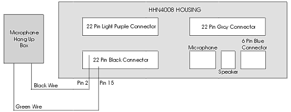
Because the Hang Up Box (HUB) black wire hooked to pin 2 which is a ground wire, it can actually be hooked to a variety of different grounded pins on the 22 pin black connector. If you use a System 90*s signaling option like the TRN6015A "Touch-Code" Mobile Selective Signaling Decoder board, the HUB will be wired to this optional board instead. The point is, actual hookups can vary from the "ideal standard" hookup. The 22 pin colored connectors are keyed to fit in the correct slot. However, the 6 pin Blue connector key unfortunately allows it to fit into the microphone slot and the microphone to fit into its slot.
The 6 pin Blue connector is optional and not used on non-DVP, 8 mode or less control heads. Some 1 and 2 mode control heads do not use the 22 pin Light Purple, 22 pin Gray or 6 pin Blue connectors (i.e. the upper control head board is not present).
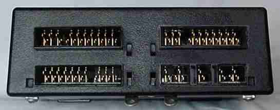
Below is a photo of the back of a HHN4008 housing with some boards in it. Please keep in mind the HHN4008 number is only for the housing. The part numbers on the boards inside the housing determine what type of control head it really is.
All of the connectors on your control cable need to be plugged in before the radio will operate. Wires that carry the switched power to the radio are usually daisy chained from one connector to the next. If one of the connectors is not plugged in, then power connections or important signal wires will have broken connections.
--
PL, Private Line, DPL, Digital Private Line, MPL, Talkaround, MDC-600, MDC-1200, MVS-20, Securenet, Smartnet, Privacy Plus, Trunked X2, Trunked X3, Touch Code, Quick Call II, Channel Scan, Talkback Scan, System 90, System 90*s, Systems 9000, Mitrek, Micor, Spectra, MataTrac, Syntor, Syntor X, Syntor X 9000 and Syntor X 9000E are trademarks of Motorola Inc.