|
|
|
|
|
|
| HKN4103A | 10', neg. ground |
| TKN8089A @ | 10', neg. ground, all modes except 32 |
| HKN4086A @ | 10', neg. ground, 32 mode, System 90*s Alternate Control Module |
| HKN4100A | 17', neg. ground, all modes and EMS |
| TKN8087A @ | 17', neg. ground, all modes except 32 |
| HKN4083A @ | 17', neg. ground, 32 mode, System 90*s Alternate Control Module |
| TKN8088A @ | 22', neg. ground, all modes except 32 and EMS |
| HKN4101A @ | 22', neg. ground, EMS |
| HKN4084A @ | 22', neg. ground, 32 mode, System 90*s Alternate Control Module |
| HKN6690A | 20' EMS Rear Control Cable |
| HKN4102A | 22', pos. ground |
| TKN8090A @ | 22', pos. ground, all modes except 32 |
| HKN4085A @ | 22', pos. ground, 32 mode, System 90*s Alternate Control Module |
| HKN4115A | 5', neg. ground, System 90*s Alternate Control Module, DVP |
| HKN4141B | 10', neg. ground, System 90*s Alternate Control Module, DVP |
| HKN4116A | 18', neg. ground, System 90*s Alternate Control Module, DVP |
| HKN4119A | 18', neg. ground, System 90*s Alternate Control Module, DVP |
| HKN4140B | 22', neg. ground, System 90*s Alternate Control Module, DVP |
| HKN4142B | 22', pos. ground, System 90*s Alternate Control Module, DVP |
| HKN4224B | 22', neg. ground, Physical Security Housing, DVP |
|
|
|
|
|
|
| HKN4051A | 30" #8 gauge Red Power Cable and Fuse kit (40 amp) |
| HKN4052A | Control Head Power Wires and Fuses |
|
|
|
|
|
|
| HKN4044A | Public Address, Orange 22 pin Connector |
| HKN4069A | MDC-600, Green 22 pin Connector |
| HKN4145A | MVS-20, Dark Blue 22 pin Connector |
| TKN6503A | QC II and Touch-Tone Decoder, Green 22 pin Connector |
| TKN6506A | Single Tone Encoder, White 22 pin Connector |
| TKN6520A | Voice Privacy Adapter, Red 22 pin Connector |
| TKN6689A | EMS, Pink 22 pin Connector |
| TKN6731A | Touch-Tone Encoder, Dark Blue 22 pin Connector |
| TKN6754A | Siren/PA, Pink 22 pin Connector |
| TKN8092A | Alternate Control Module, Gray and Light Purple 22 pin Connectors |
| TKN8096A | Alternate Control Module, Gray and Light Purple 22 pin Connectors |
| TKN8097A | Alternate Control Module, Gray and Light Purple 22 pin Connectors |
Please see the PAC page for information on the PAC-PL and PAC-RT cables.
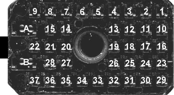
Below is a pin number locater for the radio cable connector. The view is looking towards the pins that plug into the radio's J1 connector with the cable on the left side. See the Personality Board section for information on the signals associated with this connector. Motorola's contact removal tool or a home made equivalent can be used to remove and move the number 1 through 37 contact pins in these connectors. The neoprene gasket corners must be pulled up to gain access to the 4 phillips head screws. Removing these screws allows the housing on the back of the connector to be removed. The C clip on the center screw jack must also be removed. It is difficult, actually impossible sometimes, to peel back the neoprene without damaging it. I have seen connectors where just the part of the neoprene gasket over the 4 screw heads was removed. The gasket may need to be replaced if you want to maintain the original connector sealing.
| Here are some part numbers for the J1 connector (and the retail price at the time this was written): |
|
Sometimes a radio can have intermittent operation and/or generally flakey problems that can be attributed to dirty, loose or oxidized connections on the A or B power terminals (these are connected to the large gauge red and black power wires). Checking and if needed, cleaning or repairing these connections can fix lots of different problems with these radios. Motorola started covering the back side of these 2 connections (inside the connector housing) with a glob of epoxy on later production cables (it also gets on the connector body and adjacent wires). Actually the epoxy makes repair/replacement just about impossible, but they should not have problems very often, if ever. I would not recommend using any epoxy on used cables because of the possibility of old pre-existing partially oxidized connections that you would never be able to repair again if they go bad. This tip applies to any other radio models (i.e. Syntor X 9000) and accessories (i.e. Systems 9000 siren/PA, Systems 9000 vehicle repeater, etc.) that use these connectors.
22 pin and 6 pin control head connectors:
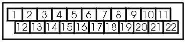
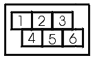
The drawing below shows the pin number locations of a 22 pin System 90, System 90*s, clamshell and 6 pin System 90*s connectors. This view is from the rear of the connector where the wires are inserted, with the top of the connector in the same position it would be in if it was plugged into the control head. These connectors are found on one end of the radio's control cable, the other end plugs into the radio.
Motorola's "contact removal tool" or a home made equivalent can be used to remove and move the wires in these connectors. Some of the connector pockets are blocked off. This is done to key the connector to a particular place in the control head, i.e. the connector will not plug into the wrong place. The exception is the 6 pin blue connector that can plug into the microphone's spot because the key pins match. The actual wiring will depend on what control head and accessories are used with the radio. If you obtain a surplus cable to use with a radio that did not come with a cable, you will probably have to rewire at least some of these wires before it works correctly. Sometimes you will have to get connectors that match your control head and accessories then wire the new connectors into the cable.
If you need connector pins, Motorola part number 09-84151B03 is a package of 5 pins that can be used on the 37 pin J1 connector, the 22 pin connectors, or 6 pin connectors or by using the contact removal tool you can salvage the end of an old cable that was chopped off (those chopped cables do have a use after all!).
| As a general rule of thumb the following color code is used on Clamshell 22 pin connectors: |
Black - Standard for all Volume/Squelch control heads, wiring varies slightly |
| As a general rule of thumb the following color code is used on System 90*s 22 pin connectors: |
Black - Standard for all Volume/Squelch control heads, wiring varies slightly |
| Here are the part numbers for the connector housings (and the retail price at the time this was written): |
I have no idea why the prices vary so wildly when the color and the keyed pins are the only difference? |
Use the following control head hookup examples as a guide to connecting the control head to the cable and accesies.
Click here for a System 90*s Hookup diagram.
Use the following cable wiring examples as a guide to cable wiring. The actual number of wires in a cable can vary and the wiring may need to be changed for your application. Use the Motorola manual Accessory Group Installation Instructions 68P81110E93 for details on how to rewire the cables. This manual also has a wiring connection diagram for the System 90*s accessories. Because these cables can be rewired in the field there may be minor differences in your wiring and the examples. This is also a very good reason to use an ohm meter instead of relying on the standard wire colors if you need to figure out how your cable is wired.
Click here for a Clamshell 32/16/8 mode basic wiring example.
Click here for a Clamshell 32/16 mode + scan head wiring example.
Click here for a System 90*s 32/16/8 mode basic wiring example.
Click here for a System 90*s 8 mode scan wiring example.
Click here for a System 90*s 32/16 mode scan wiring example.
Click here for a System 90*s 32/16 mode scan + MPL head wiring example.
Click here for a System 90*s 32/16/8 mode + scan head wiring example.
The above examples using the scan head (operator select non-priority scan) and MPL head (operator select PL/DPL) have the same wiring (the only difference is the lt. purple connector pin 1 is only connected on the scan head and not used on the MPL head). It is fairly easy to use these examples to figure out how to wire these heads for configurations that are not covered by the examples by borrowing the wiring for a particular head from one example and grafting it into another example. It is also easy to see how to add up to 3 additional scan boards (only one board would have the Channel Scan Enable wired) or an additional MPL board using the daisy chaining provided by the gray and lt. purple connectors. The TRN4332A and TRN4336A Scan Indicators are wired like the scan head without the Channel Scan Enable wire.
Standard DVP cable wiring is covered in the Securenet Supplement 68P80100W31 manual. There are variations on DVP cable wiring that may be contained in specific DVP manuals. Hand Held Control Head (HHCH) cables including HHCH DVP are covered in Hand Held Control Head 68P80100W43 manual.
In general, Motorola Syntor X part numbers that start with a "Y" are special order variations of standard parts (i.e. YKN4103A cable would be a factory customized variation of the HKN4103A cable). These parts may or may not be useful. You will have to figure them out on your own unless you are fortunate enough to get the documentation with them.
--
PL, Private Line, DPL, Digital Private Line, MPL, Talkaround, MDC-600, MDC-1200, MVS-20, Securenet, Smartnet, Privacy Plus, Trunked X2, Trunked X3, Touch Code, Quick Call II, Channel Scan, Talkback Scan, System 90, System 90*s, Systems 9000, Mitrek, Micor, Spectra, MataTrac, Syntor, Syntor X, Syntor X 9000 and Syntor X 9000E are trademarks of Motorola Inc.