Syntor X radio - control head communication scheme:
The Syntor X radio uses 12 mode lines that can be connected to control heads and System 90*s accessories. These mode lines will be referred to as M1 (mode line 1), M2 (mode line 2), M10 (mode line 10) and so on. All 12 mode lines are physically capable of sending or receiving data. In addition to the 12 mode lines there is a signal called "control head strobe". This signal is generated by the radio and is used to control different control heads and System 90*s accessories.
The communication scheme created by Motorola for the mode lines and control head strobe is as follows: Mode lines 9 through 12 (M9-M12) of the radio's bi-directional bus act as an address system when the Control Head Strobe signal is acting as chip enable and mode lines 1 through 8 (M1-M8) are acting as a bi-directional data bus. The exception is when the control head strobe is high, the radio can read the current mode setting (Mode Select) from the control head.
As far as I know, all of the control heads and System 90*s accessories that use this communication scheme are unique to the Syntor X radio line.
When the radio drawer internal version of the Hand Held Control Head (HHCH) is used, the entire Syntor X Personality Board control head interface is changed by the HLN4728A Computer Board that internally plugs into the Syntor X Personality Board. None of the information on this page applies to the HHCH external interface. The internal HLN4728A Computer Board does use the interfaces described below, except for Operator Select Coded Squelch Encode and Decode. There is a variety of Syntor X HHCH configurations available. They are customized for scan, DVP and other options.
| SYNTOR X CONTROL HEAD AND SYSTEM 90*s ACCESSORY COMMUNICATION |
||||||
|
DATA in/out |
|
|
|
|||
| M9 | M10 | M11 | M12 | |||
| 0 | 0 | 0 | 0 | not used | ||
| 1 | 0 | 0 | 0 | not used | ||
| 0 | 1 | 0 | 0 | not used | ||
| 1 | 1 | 0 | 0 | not used | ||
| 0 | 0 | 1 | 0 | not used | ||
| out | 1 | 0 | 1 | 0 | Low | Display (output) |
| 0 | 1 | 1 | 0 | not used | ||
| 1 | 1 | 1 | 0 | not used | ||
| in | 0 | 0 | 0 | 1 | Low | Operator Select Mode Scan, Modes 1-8 |
| in | 1 | 0 | 0 | 1 | Low | Operator Select Mode Scan, Modes 9-16 |
| in | 0 | 1 | 0 | 1 | Low | Operator Select Mode Scan, Modes 17-24 |
| in | 1 | 1 | 0 | 1 | Low | Operator Select Mode Scan, Modes 25-32 |
| in | 0 | 0 | 1 | 1 | Low | Operator Select Coded Squelch Encode |
| 1 | 0 | 1 | 1 | not used | ||
| in | 0 | 1 | 1 | 1 | Low | Operator Select Coded Squelch Decode |
| in | 1 | 1 | 1 | 1 | High | Mode Select (default state) |
All of the above System 90*s operator select optional accessories require special programming in the radio's EEPROM and may also require different Personality Board jumper settings and J1 cable connections.
|
|
||||||||
| M1 | M2 | M3 | M4 | M5 | M6 | M7 | M8 | Description |
| 0 | 1 | 1 | 1 | 1 | 1 | 1 | 1 | Select Mode 1 |
| 1 | 0 | 1 | 1 | 1 | 1 | 1 | 1 | Select Mode 2 |
| 1 | 1 | 0 | 1 | 1 | 1 | 1 | 1 | Select Mode 3 |
| 1 | 1 | 1 | 0 | 1 | 1 | 1 | 1 | Select Mode 4 |
| 1 | 1 | 1 | 1 | 0 | 1 | 1 | 1 | Select Mode 5 |
| 1 | 1 | 1 | 1 | 1 | 0 | 1 | 1 | Select Mode 6 |
| 1 | 1 | 1 | 1 | 1 | 1 | 0 | 1 | Select Mode 7 |
| 1 | 1 | 1 | 1 | 1 | 1 | 1 | 0 | Select Mode 8 |
|
|
||||||||
| M1 | M2 | M3 | M4 | M5 | M6 | M7 | M8 | Description |
| 0 | 0 | 0 | 0 | 0 | 0 | 0 | 0 | Select Mode 1 |
| 1 | 0 | 0 | 0 | 0 | 0 | 0 | 0 | Select Mode 2 |
| 0 | 1 | 0 | 0 | 0 | 0 | 0 | 0 | Select Mode 3 |
| .... | .... | .... | .... | .... | 0 | 0 | 0 | .... |
| 1 | 0 | 1 | 1 | 1 | 0 | 0 | 0 | Select Mode 30 |
| 0 | 1 | 1 | 1 | 1 | 0 | 0 | 0 | Select Mode 31 |
| 1 | 1 | 1 | 1 | 1 | 0 | 0 | 0 | Select Mode 32 |
| 0 | 0 | 0 | 0 | 0 | 1 | 0 | 0 | Select Mode 33 |
| 1 | 0 | 0 | 0 | 0 | 1 | 0 | 0 | Select Mode 34 |
| 0 | 1 | 0 | 0 | 0 | 1 | 0 | 0 | Select Mode 35 |
|
.... |
.... |
.... |
.... |
.... |
1 | 0 | 0 | .... |
| 1 | 0 | 1 | 1 | 1 | 1 | 0 | 0 | Select Mode 62 |
| 0 | 1 | 1 | 1 | 1 | 1 | 0 | 0 | Select Mode 63 |
| 1 | 1 | 1 | 1 | 1 | 1 | 0 | 0 | Select Mode 64 |
The Mode Select selects the current operating mode of the Syntor X radio. Selecting the operating mode also selects everything programmed in the EEPROM for that mode (i.e. Rx and Tx frequencies, Rx and Tx PL/DPL, squelch type, priority scan list, non-priority scan list, Tx time out timer, etc.). You can select one of 32 possible modes (here is the information on 64 mode operation). In older Motorola Radios this control would have only selected the frequency and would have been called a channel selector. Because this control does so much more on the Syntor X radios, Motorola decided to call it a mode selector.
When clamshell Mode Select control heads are combined with System 90*s accessories that use the mode lines, the System 90*s board provides a logically inverted "control head strobe" signal called "mode strobe". This "mode strobe" signal is used by the clamshell control head in conjunction with its mode line diodes to cause the clamshell control head to release the mode lines whenever the "mode strobe" is high. If the clamshell does not release the mode lines then it will interfere with data being transferred on the M1-M8 mode lines.
The only time the radio uses the mode lines for Mode Select is when the control head strobe signal is high (the inverted mode strobe is low). If the control head strobe signal is low (mode strobe is high) then we know the radio is not accessing the Mode Select control head. This condition is used to allow properly configured clamshell control heads (using the Mode Strobe signal) to release the M1 - M8 mode lines at the correct time, without the clamshell ever decoding the M9-M12 mode lines. This same "mode strobe" arrangement is used by the System 90*s Mode Select control head bank switch (R/D, A/B, A/B/C/D) boards.
If the radio is programmed to use "operator select mode scan", "operator select coded squelch" (encode or decode), has the J1-33 Display Enable line grounded or JU14 Personality Board jumper set then the mode lines will be used for more than just "mode select". When this happens the Mode Select control head must be fully Syntor X compatible. If all of the above conditions are not present the Mode Select control head can be from other Motorola radio lines (Syntor, Mitrek, Micor, etc.) because the mode lines will only be used for Mode Select (in this case scanning will be a problem because there is no way to display what mode the scan stops on).
|
|
||||||||
| M1 | M2 | M3 | M4 | M5 | M6 | M7 | M8 | Selected Light Description |
| 0 | 0 | 0 | 0 | 0 | x | 0 | x | Mode 1 Light Mode Display |
| 1 | 0 | 0 | 0 | 0 | x | 0 | x | Mode 2 Light Mode Display |
| .... | .... | .... | .... | .... | x | 0 | x | .... |
| 0 | 1 | 1 | 1 | 1 | x | 0 | x | Mode 31 Light Mode Display |
| 1 | 1 | 1 | 1 | 1 | x | 0 | x | Mode 32 Light Mode Display |
| 0 | 0 | 0 | 0 | 0 | x | 1 | x | Mode 1 Light Scan Display |
| 1 | 0 | 0 | 0 | 0 | x | 1 | x | Mode 2 Light Scan Display |
| .... | .... | .... | .... | .... | x | 1 | x | .... |
| 0 | 1 | 1 | 1 | 1 | x | 1 | x | Mode 31 Light Scan Display |
| 1 | 1 | 1 | 1 | 1 | x | 1 | x | Mode 32 Light Scan Display |
| x | x | x | x | x | x | x | 0 | PRI "Scan Switch" Light Off |
| x | x | x | x | x | x | x | 1 | PRI "Scan Switch" Light On |
Display Function is only used by System 90*s optional boards that have display or indicators. These boards have varying jumper settings that must be set correctly. Use the proper System 90*s service manuals to lookup the correct jumpering. In addition the J1-33 Display Enable line must be grounded or the radio's Personality Board JU14 must be installed. If the Display Enable is not activated then the radio will not send any Display Function information to the System 90*s accessories.
This "display function" is the source of the false mode 32 display. In order to filter out a false mode 32 display the PTT and Squelch Tail signals must be taken into account. Remember, the false mode 32 display can only adversely affect incorrectly configured 32 mode Mode Select control heads that use the display function and the operator select non-priority mode scan control or display head when it's jumpered for bank D.
When scanning, the PRI light will blink when stopped on an active secondary priority scan. It will remain on, when stopped on an active primary priority scan.
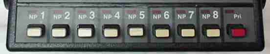
Operator select non-priority scan boards:
| OPERATOR SELECT MODE SCAN | |
| M1 | 0 = Selects Non-Priority Scan for Mode 8, 16, 24 or 32 - NP8 Button |
| M2 | 0 = Selects Non-Priority Scan for Mode 7, 15, 23 or 31 - NP7 Button |
| M3 | 0 = Selects Non-Priority Scan for Mode 6, 14, 22 or 30 - NP6 Button |
| M4 | 0 = Selects Non-Priority Scan for Mode 5, 13, 21 or 29 - NP5 Button |
| M5 | 0 = Selects Non-Priority Scan for Mode 4, 12, 20 or 28 - NP4 Button |
| M6 | 0 = Selects Non-Priority Scan for Mode 3, 11, 19 or 27 - NP3 Button |
| M7 | 0 = Selects Non-Priority Scan for Mode 2, 10, 18 or 26 - NP2 Button |
| M8 | 0 = Selects Non-Priority Scan for Mode 1, 9, 17 or 25 - NP1 Button |
Up to 4 of the HLN4290A boards may be used. Each board must be uniquely jumpered for 1 of 4 possible A/B/C/D mode banks. The priority and non-priority scan modes only work when the PRI button is selected and the currently selected mode has been programmed for operator select scanning in the EEPROM. In some radios Personality Board jumper JU1 may be installed. This has the same effect as always having the PRI button selected.
For each mode, the radio's internal EEPROM non-priority scan list may be selected or the operator select mode non-priority scan may be selected. Using one precludes using the other. In other words you can use the internal EEPROM list or the operator select mode NP buttons, but never both in the same mode.
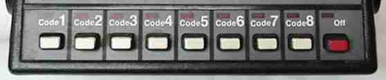
Operator select multiple PL/DPL (MPL) boards:
| Operator Select Coded Squelch Encode and Decode | |||
| M1 | M2 | M3 | M1-M3 Selects one of 8 PL/DPL Codes - Set by front panel push buttons |
| 0 | 0 | 0 | Code 1 Button |
| 1 | 0 | 0 | Code 2 Button |
| 0 | 1 | 0 | Code 3 Button |
| 1 | 1 | 0 | Code 4 Button |
| 0 | 0 | 1 | Code 5 Button |
| 1 | 0 | 1 | Code 6 Button |
| 0 | 1 | 1 | Code 7 Button |
| 1 | 1 | 1 | Code 8 Button |
| M4 | M5 | M6 | M4-M6 Selects one of 8 PL/DPL Banks - Set by Jumpers JU8, JU9 and JU10 |
| 0 | 0 | 0 | Bank 1 (modes 1-8) Bank A on the System 90*s Control Head |
| 1 | 0 | 0 | Bank 2 (modes 9-16) Bank B on the System 90*s Control Head |
| 0 | 1 | 0 | Bank 3 (modes 17-24) Bank C on the System 90*s Control Head |
| 1 | 1 | 0 | Bank 4 (modes 25-32) Bank D on the System 90*s Control Head |
| 0 | 0 | 1 | Bank 5 (modes 33-40, normally unused EEPROM space) |
| 1 | 0 | 1 | Bank 6 (modes 41-48, normally unused EEPROM space) |
| 0 | 1 | 1 | Bank 7 (modes 49-56, normally unused EEPROM space) |
| 1 | 1 | 1 | Bank 8 (modes 57-64, normally unused EEPROM space) |
|
|
Special Customer Applications Only, Normally Jumpered = 0 | ||
|
|
1 = "MPL Off Switch" Pushed In (ON), 0 = "MPL Off Switch" Pushed Out (OFF) | ||
The most common use of these boards is a single board jumpered to perform both encode and decode. When the board is selected with the "MPL Off Switch" pushed in (ON) and the currently selected mode in the EEPROM is programed to use operator select encode or decode, the PL/DPL code selected by the board will be used. If the "MPL Off Switch" pushed out (OFF) or the currently selected mode in the EEPROM is not programmed to use operator select encode or decode, the selected MPL code will be ignored and the radio will use the default encode and decode PL/DPL codes normally programmed for the selected mode (if any).
In other words this board allows you to choose between the normal PL/DPL programming each mode already has or 1 of 8 PL/DPL codes selected by the user (using the "code" buttons and "off" button). This is commonly used in commercial radio systems to select different repeaters that share a common frequency.
--
PL, Private Line, DPL, Digital Private Line, MPL, Talkaround, MDC-600, MDC-1200, MVS-20, Securenet, Smartnet, Privacy Plus, Trunked X2, Trunked X3, Touch Code, Quick Call II, Channel Scan, Talkback Scan, System 90, System 90*s, Systems 9000, Mitrek, Micor, Spectra, MataTrac, Syntor, Syntor X, Syntor X 9000 and Syntor X 9000E are trademarks of Motorola Inc.