Mike Blenderman, K7IC passed in 2022. This December 2021 mirror
of his onfreq.com site was extracted from the Wayback Machine.
SYNTOR EPROM PROJECT
[SYNTOR] [SYNTOR
X] [SYNTOR X 9000 and X
9000E] [TRUNKING SYNTOR
X and SYNTOR X 9000] [SPECTRA]
[PL] [DPL] [PAC-PL
and PAC-RT VEHICLE REPEATERS][HHCH] [PROM
PROGRAMMERS] [POWER
WIRING]
[GLOSSARY]
[WEB LINKS] [SURPLUS
PARTS GUIDE] [ITEMS FOR SALE]
[WEB SITE REVISIONS]
The parts used for the project are:
1 - 16 pin DIP parts header
1 - 24 pin DIP socket
1 - piece of standard .1 inch perforated board (cut to size)
2 - plastic printed circuit board standoffs
2 - small miscellaneous screws
miscellaneous 26 and 22 gage wires
epoxy
1 - 2716 or 27C16 EPROM
Soldering is required for this project. The common plastic
16 pin DIP headers tend to melt if the solder iron tip is held
on a pin too long, so quick efficient soldering is required. Since
I am right handed (my soldering iron hand) I found it easiest
to start with the 16 pin DIP header pins on my left and work across
one pin at a time (i.e. pins 9-16 and pins 1-8). Because pins
10 through 12 and pin 15 have to cross to the other side on the
24 pin DIP socket I found it easier to start wiring with 16 pin
DIP header pins 9 through 16.
Depending on the parts you have or can find you may have to
improvise. I found all these parts just by cruising up and down
the isles at a local electronics supply company.
First the perforated board was cut to size (see photos).
Then the printed circuit board standoffs were cut down
(they were originally too long) and screwed to the perforated
board. Next the standoffs were glued to the 16 pin
DIP parts header. Then the 24 pin DIP socket was placed
on the perforated board and the pins were wired from point
to point. The 22 gage wire was used for the Vcc and Gnd1 pins. The 26 gage wire was used for
all the other pins. Be sure to check for clearance with components
on the Syntor circuit board when cutting the standoffs
to size.
Here is the wiring diagram:
Just connect all of the identicaly named pins (ignore the information
in light gray) from the 16 pin header to the 24 pin socket.
The Vcc and Vpp on the 24 pin socket are also connected together.
nc - not connected (the original PROM is only 4 bits wide)
Here are the EPROM converter photos:
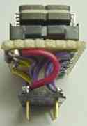
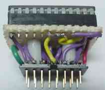
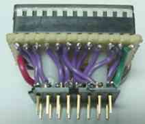
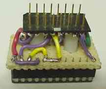
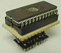
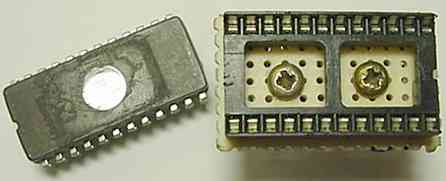
Photos by: Max KK7HI
Please take note that pin 1 on the 16 pin DIP header is shaved
(this one came that way) and the 24 pin DIP socket above it oriented
with its pin 1 orientation notch above the 16 pin header pin 1
end. When the 24 pin EPROM is installed, its pin 1 orientation
notch matches the pin 1 orientation notch in the 24 pin socket
and the 16 pin header is plugged in with its pin 1 where the old
PROM pin 1 would have gone. This is done on purpose to avoid confusion
about orienting pin 1 correctly on the EPROM and when plugging
it into the Syntor socket. The Syntor 16 pin socket can be hard
to see when plugging in the conversion assembly so using a flashlight
is recommended to help visually verify the 16 pin header is correctly
installed in the Syntor 16 pin socket.
The EPROM converters are a bit labor intensive to build, but
they will forever free you from trying to find and program those
old PROMs. Needless to say the larger EPROM will provide up to
32 channels and they are so common almost all programmers will
program them. After the conversion you can erase the EPROM with
an ultraviolet eraser and reprogram it rather then the old method
of having to throw out the old disposable PROMs and then find
and program brand new PROMs.
It does not look pretty, but it does not have to look pretty
to get the job done.
To enable 32 channel operation JU1101 (near the old PROM) will
have to be removed. When it is installed it grounds address line
A8 and only allows 16 channel operation. A 32 channel control
head and cable with 12 frequency select lines is required for
proper operation when JU1101 is removed.
[SYNTOR] [SYNTOR
X] [SYNTOR X 9000 and X
9000E] [TRUNKING SYNTOR
X and SYNTOR X 9000] [SPECTRA]
[PL] [DPL] [PAC-PL
and PAC-RT VEHICLE REPEATERS][HHCH] [PROM
PROGRAMMERS] [POWER
WIRING]
[GLOSSARY]
[WEB LINKS] [SURPLUS
PARTS GUIDE] [ITEMS FOR SALE]
[WEB SITE REVISIONS]
[TOP] [SYNTOR
HOME]
[HOME]
--
PL, Private Line, DPL, Digital Private Line,
MPL, Talkaround, MDC-600, MDC-1200, MVS-20, Securenet, Smartnet,
Privacy Plus, Trunked X2, Trunked X3, Touch Code, Quick Call II,
Channel Scan, Talkback Scan, System 90, System 90*s, Systems 9000,
Mitrek, Micor, Spectra, MataTrac, Syntor, Syntor X, Syntor X 9000
and Syntor X 9000E are trademarks of Motorola Inc.